
Shroud segment for a turbomachine

a turbomachine and shroud technology, applied in the direction of machines/engines, climate sustainability, natural mineral layered products, etc., can solve the problems of inability to cool or cool the coating, and achieve the effects of enhancing efficiency, good thermal insulation characteristics, and low thermal conductivity coefficien

Active Publication Date: 2009-01-20
ROLLS ROYCE DEUT LTD & CO KG
View PDF27 Cites 29 Cited by
  • Summary
  • Abstract
  • Description
  • Claims
  • Application Information

AI Technical Summary

Benefits of technology

The present invention provides a solution for designing a rubbing coating for turbomachines that can withstand high temperatures and maintain a narrow sealing gap between blade tips and the flow duct wall. The rubbing coating is cooled from the rear side of the metallic substrate to which it is bonded, using a high-temperature resistant, but thermally conductive ceramic material with a high coefficient of thermal conductivity. The ceramic material is bonded to the substrate using a spatially arranged bond coat or an additional overlay, creating a strong interlock between the ceramic layer and the substrate. The invention allows components, such as rotor wheels in aircraft engines, to operate at very high working gas temperatures with enhanced efficiency.

Problems solved by technology

On the other hand, with very high gas temperatures and / or large coating thicknesses and the resultant need for cooling due to the self-insulating effect of the zirconium oxide and in connection with the coating thickness actually required for abrasion of the rubbing coating, such coatings cannot be cooled, or cannot be cooled as necessary for the correspondingly high working gas temperatures, even if high cooling medium flow rates are used.

Method used


Image

  • Shroud segment for a turbomachine
  • Shroud segment for a turbomachine
  • Shroud segment for a turbomachine

Examples


Embodiment Construction

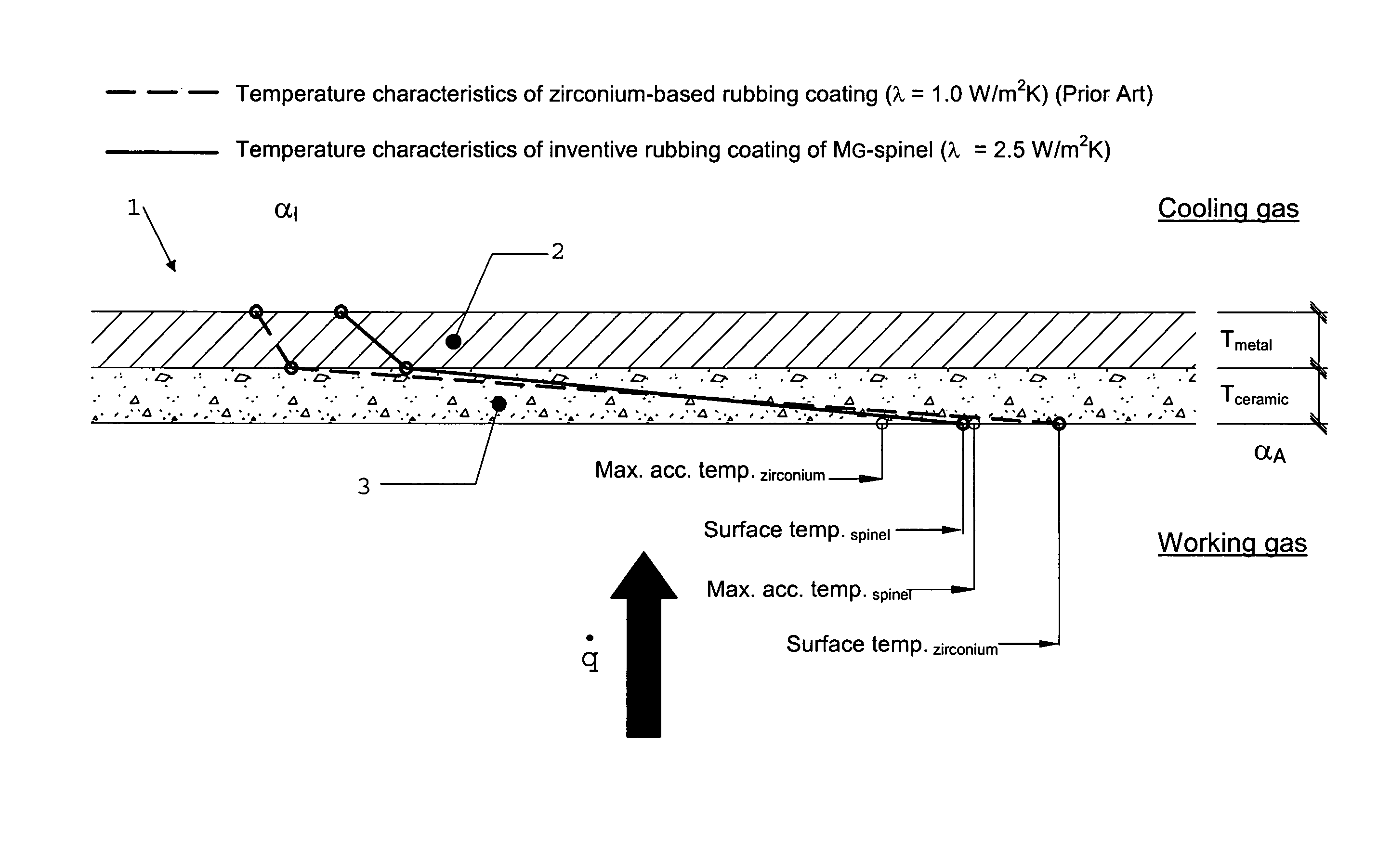
[0019]This detailed description should be read in combination with the summary above. As shown in FIG. 1, the stationary shroud segment 1 comprises a metallic support 2 (substrate) to which a rubbing coating 3 of a high-temperature resistant ceramic material firmly adheres. The turbine blade tips mating with the rubbing coating 3 with a small clearance are not shown on the drawing. Working gas, which is fed via a stator vane from the combustion chamber (not illustrated) of an aircraft engine flows with a certain temperature (Tempworking gas), which, for example, can be 1500° C., along the rubbing coating 3, while a cooling gas with a temperature (Tempcooling gas) flows at the rear side of the metallic support 2 of the shroud segment 1. The specific heat flux in the direction of the bold arrow is:

[0020]q.=k⁡(Tempworking⁢⁢gas-Tempcooling⁢⁢gas),

with k being the coefficient of heat transmission resulting from the coefficients of heat transfer on the working gas side or on the cooling ga...


PUM

PropertyMeasurementUnit
thicknessaaaaaaaaaa
temperatureaaaaaaaaaa
thermally conductiveaaaaaaaaaa

Abstract

On an aircraft engine with a shroudless rotor wheel arranged in a flow duct, the flow duct includes a shroud segment (1) formed by a ceramic rubbing coating (3) which, while having good thermal conductivity, is highly-temperature resistant, attaches firmly to the metallic substrate (2) and is abradable by the tips of the rotor wheel to form a sealing gap as narrow as possible, this rubbing coating, owing to the lack of self-insulation, being coolable from a free side of the metallic substrate and, therefore, permitting for working gas temperatures occurring in high-pressure turbines and coating thicknesses sufficient for abrasion.

Description

[0001]This application claims priority to German Patent Application DE10334698.8, filed Jul. 25, 2004, the entirety of which is incorporated by reference herein.BACKGROUND OF THE INVENTION[0002]This invention relates to a shroud segment for a turbomachine, in particular an aircraft engine, with a flow duct and a bladed rotor wheel arranged in the flow duct which perform a relative rotary movement and are flown by a hot working gas, with the shroud segment comprising a metallic substrate provided by the flow duct and a ceramic rubbing coating which is bonded to the inner surface of the substrate and is abradable by the blade tips for the formation of a narrow sealing gap.[0003]On turbomachinery, for example aircraft engines or stationary gas turbines, the sealing gap between the tips of the rotor blades fitted to a rotor and the inner surface of a casing surrounding these rotor blades must be minimized to achieve high efficiency. As is known, the required minimum sealing gap width is...

Claims


Application Information

Patent Timeline
Patent Type & Authority Patents(United States)
IPC IPC(8): B32B18/00B32B15/04C23C4/10C23C28/04C23C30/00F01D11/12
CPCC23C4/105C23C28/042C23C28/044C23C28/048C23C30/00F01D11/12F01D11/125Y10T428/12611Y02T50/67F05D2240/11F05D2230/90F05D2300/611F05D2300/125F05D2300/5024C23C4/11Y10T428/249967Y02T50/60
Inventor ROTH-FAGARASEANU, DANWUNDERLICH, THOMAS
Owner ROLLS ROYCE DEUT LTD & CO KG
Learn More