Lubrication device of four-stroke engines

a lubrication device and engine technology, applied in the direction of lubrication elements, pressure lubrication, auxilary lubrication, etc., can solve the problems of affecting the effective combustion of air, unable to pass some standards and regulations of pollution emissions, and exhaust fume pollution, so as to avoid the problems of lubricant consumption and air filter contamination

Active Publication Date: 2009-01-27
IND TECH RES INST
View PDF8 Cites 6 Cited by
  • Summary
  • Abstract
  • Description
  • Claims
  • Application Information

AI Technical Summary

Benefits of technology

[0021]In view of the above, the lubrication device of four-stroke engine of the present invention mainly has the rocker arm room and the crank case connect to each other, and the alternating design of the oil supply and oil-absorption channels enables lubricant mists to cycle from the crank case through the rocker arm room to cam room and then to be re-absorbed into the crank case, thereby allowing engine to be manipulated at various angles; also the design of the oil supply path and the oil recycling path provides proper lubrication, and in accordance with the design of eccentric apertures and airtight oil plugs, situation of excess lubricant flowing out of the crank case can be avoided, thereby avoiding consequent problems of excessive lubricant consumption and engine piston jammed in cylinder caused by insufficient lubrication; in addition, the design of the exhaust channel employs centrifugal force to prevent oil drops or massive oil mists from entering, thereby avoiding problems of lubricant consumption and air filter contamination caused by massive lubricant flowing out through the respiratory pipe.

Problems solved by technology

When a foresaid two-stroke engine is operating, it emits exhaust fume and takes in air at the same time; in this situation, the emitted exhaust fume contains some fuel unburned or incompletely burned, and it means that using the two-stroke engine will cause exhaust fume pollution; therefore, it cannot pass some of the standards and regulations of pollution emissions recently issued.
Although four-stroke engines have advantages of less noise and lower emission pollution, they have disadvantage as well; cams and valves of the four-stroke engines require proper lubrication; therefore, a four-stroke engine must be integrated with a lubrication device; however, when a four-stroke engine integrated with a lubrication device and is applied to a work machine, such as a chain saw or others, due to the practical application environment, user is likely to manipulate the four-stroke engine at an extremely slanting or even upside down angle, and at this moment, lubricant stored inside crank case of the lubrication device is likely to flow into exhaust valves as well as flow path of air mixture in the combustion air, thereby further interfering with effective air combustion and causing engine oil leakage.
As shown in FIG. 2, a lubrication device of four-stroke engines is disclosed according to U.S. Pat. No. 6,170,456, which mainly allocates a stirring chamber 14 on a long and narrow concave underneath the crank case 13, and also forms an oil hole 15 at a bottom of the stirring chamber 14 in communication with an engine oil tank; although this kind of design is capable of preventing massive lubricant from flowing into the crank case when the engine is at a slanting angle, it is not capable of providing other mechanical parts of machine, such as cam and gas valves and others, with effective lubrication when the engine is operationally turning over for a long time period; in addition, the traditional respiratory pipe that is externally connecting to air filter generally is not commonly allocated with filter therein, therefore, when the engine is operating at a slanting angle, lubricant is likely to flow out via the respiratory pipe, thereby causing problems of unnecessary lubricant consumption and air filter contamination.
Hence, it is a highly urgent issue in the industry for how to provide a lubrication device of four-stroke engines, which is capable of enabling lubricant to flow into valve chamber and cam room to provide effective lubrication, and meanwhile preventing massive lubricant from flowing into air-intake system and thus the cylinder, consequently causing engine extinguished, thereby allowing users to manipulate engine at various angles.

Method used


Image

  • Lubrication device of four-stroke engines
  • Lubrication device of four-stroke engines
  • Lubrication device of four-stroke engines

Examples


Embodiment Construction

[0035]The following illustrative embodiments are provided to illustrate the disclosure of the present invention, these and other advantages and effects can be apparently understood by those in the art after reading the disclosure of this specification. The present invention can also be performed or applied by other different embodiments. The details of the specification may be on the basis of different points and applications, and numerous modifications and variations can be devised without departing from the spirit of the present invention.

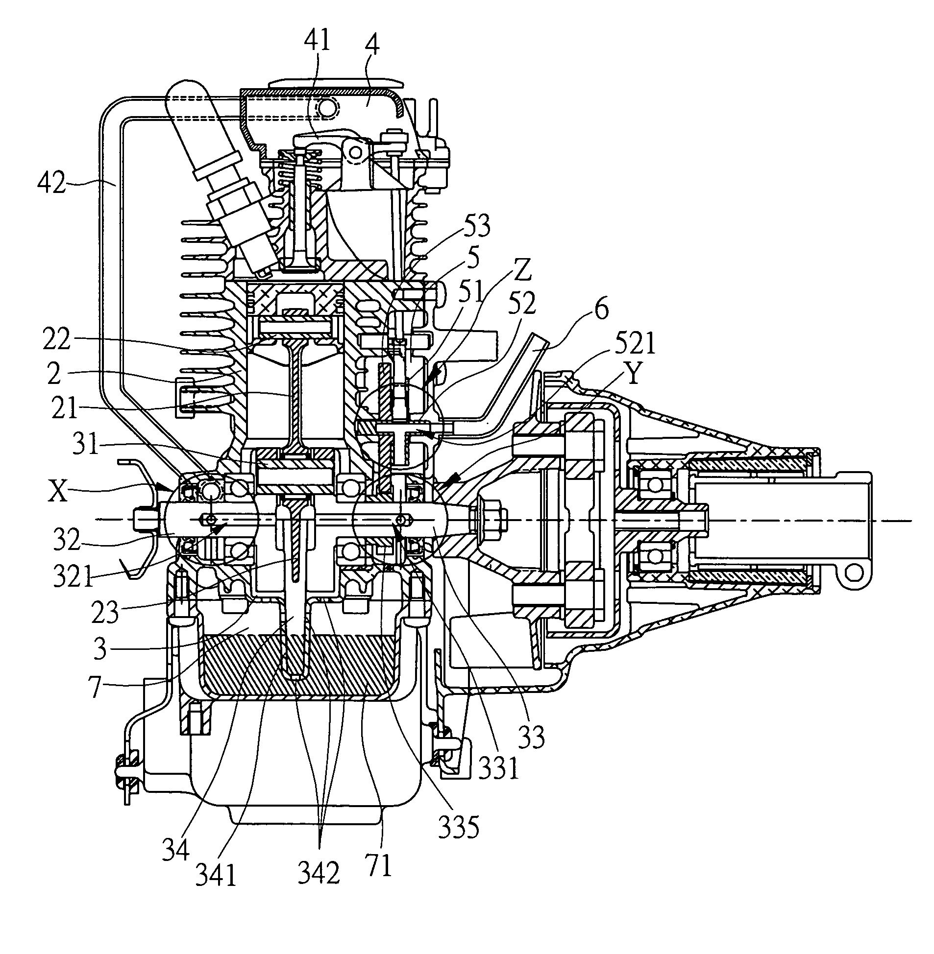
[0036]As shown in FIGS. 3A and 3B, the lubrication device of four-stroke engines of the present invention is applicable to four-stroke engines that at least have a cylinder 2, a crank case 3, a rocker arm room 4 and a cam room 5 that are connecting to each other, and a respiratory pipe 6, thereby enabling lubricant mist to be cycling from the crank case 3 through the rocker arm room 4 to the cam room 5 and then be absorbed back to the crank case ...


PUM


Abstract

A lubricant device of four-stroke engine is provided according to the present invention. The lubricant device is applicable to a four-stroke engine having a cylinder, a crank case, a rocker arm room and a cam room connected to the rocker arm room. The lubricant device mainly has the rocker arm room and the crank case be connected to each other, and the design of alternating oil supply and oil recycling channels enables lubricant mists to cycle from the crank case through the rocker arm room to the cam room and then be re-absorbed into the crank case, thereby allowing engines to be manipulated at various angles.

Description

BACKGROUND OF THE INVENTION[0001]1. Field of the Invention[0002]This invention generally relates to four-stroke engine, and more specifically, to a lubrication device that is applicable to four-stroke engines.[0003]2. Description of Related Art[0004]In order to provide common portable work machines, such as lawn mowers, chain saws, and other trimmers with sufficient torque and long-term power, modern industry adopts designs that employ engines of internal combustion as power source. However, the foresaid portable work machines are commonly manipulated at various angles, for instance, a chain saw must be manipulated at various angles in accordance with a specific practical object to be cut, but not maintaining at a same angle; beside, to answer the manual manipulation demands of light weight and high rotation speed, two-stroke engines are preferable selections of internal combustion engine to four-stroke engines theoretically.[0005]When a foresaid two-stroke engine is operating, it e...

Claims


Application Information

Patent Timeline
Patent Type & Authority Patents(United States)
IPC IPC(8): F01M1/02F01M11/02F01M9/10
CPCF01M9/06F01M11/02F01M11/064F01M2001/062F01M2011/023
Inventor LI, SHAO-YULIN, YEU-JOUGU, HUAN-LUNGCHANG, CHI-WEI
Owner IND TECH RES INST
Why Eureka
Try Eureka