
Tissue graft support apparatus

a tissue graft and support device technology, applied in the field of tissue graft support devices, can solve the problems of desiccation, time-consuming and expensive, tedious and time-consuming, etc., and achieve the effect of keeping the flow smooth and facilitating the placement of grafts more quickly

Active Publication Date: 2009-01-27
KEENE SHARON
View PDF13 Cites 13 Cited by
  • Summary
  • Abstract
  • Description
  • Claims
  • Application Information

AI Technical Summary

Benefits of technology

[0011]The compartments are designed to hold saline in which follicular unit grafts are placed. This permits the surgeon to separate various size grafts while maintaining hydration. In use, an individual graft, which may comprise one or several hair follicles is separated or pulled from a compartment to an associated channel or spout where the graft may then be gripped with forceps, removed and transplanted immediately to the patients recipient scalp area. Another feature of the compartments is the efficient use of space eliminating waste and compacting the storage area of the grafts. Unlike Petri dishes where hydration solution covers a relatively large area in comparison to the grafts, and requires several milliliters of fluid, each compartment requires only a small amount of fluid to maintain graft immersion for hundreds of hairs. This latter feature is particular advantageous in that it permits efficient use of more expensive solutions which recently have been developed which improve graft survival.

Problems solved by technology

The one physical insult that can most impact graft survival is desiccation.
Because of the risk of desiccation, most of the grafts are left in the Petri dish until just prior to placement.
As will be appreciated, this is tedious and time consuming.
Thus, it is time consuming and expensive.
The tray does not allow for significant or immersible hydration of the grafts, although there is some.
The tray has a limited graft holding capacity.
The design limits the operator's ability to utilize the hand which holds the Banuchi implanter, leaving it unavailable to perform any other function while doing this task.
Also, should the operator loosen their grip or the tray slip, grafts are at risk for spillage.
This device reportedly is prone to jamming during use, has a limited capacity to hold grafts, has no capacity to keep grafts immersed in hydrating solution, and also is hand held.
However, once the Eisenberg tray is removed from storage for use, there is nothing to retain the saline around the grafts, and the grafts are prone to dehydration.
The drainage holes in the tray actually prevent immersible hydration from occurring and subject grafts to potential dessication during the insertion process of placement.
Also, many users find the ring retention design of the Eisenberg support tray to be somewhat uncomfortable.

Method used


Image

  • Tissue graft support apparatus
  • Tissue graft support apparatus
  • Tissue graft support apparatus

Examples


Embodiment Construction

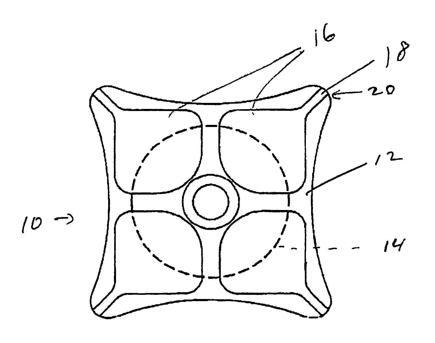
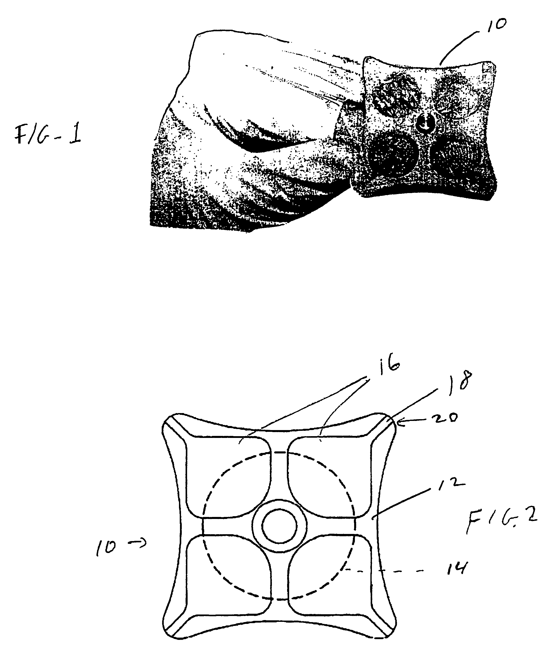
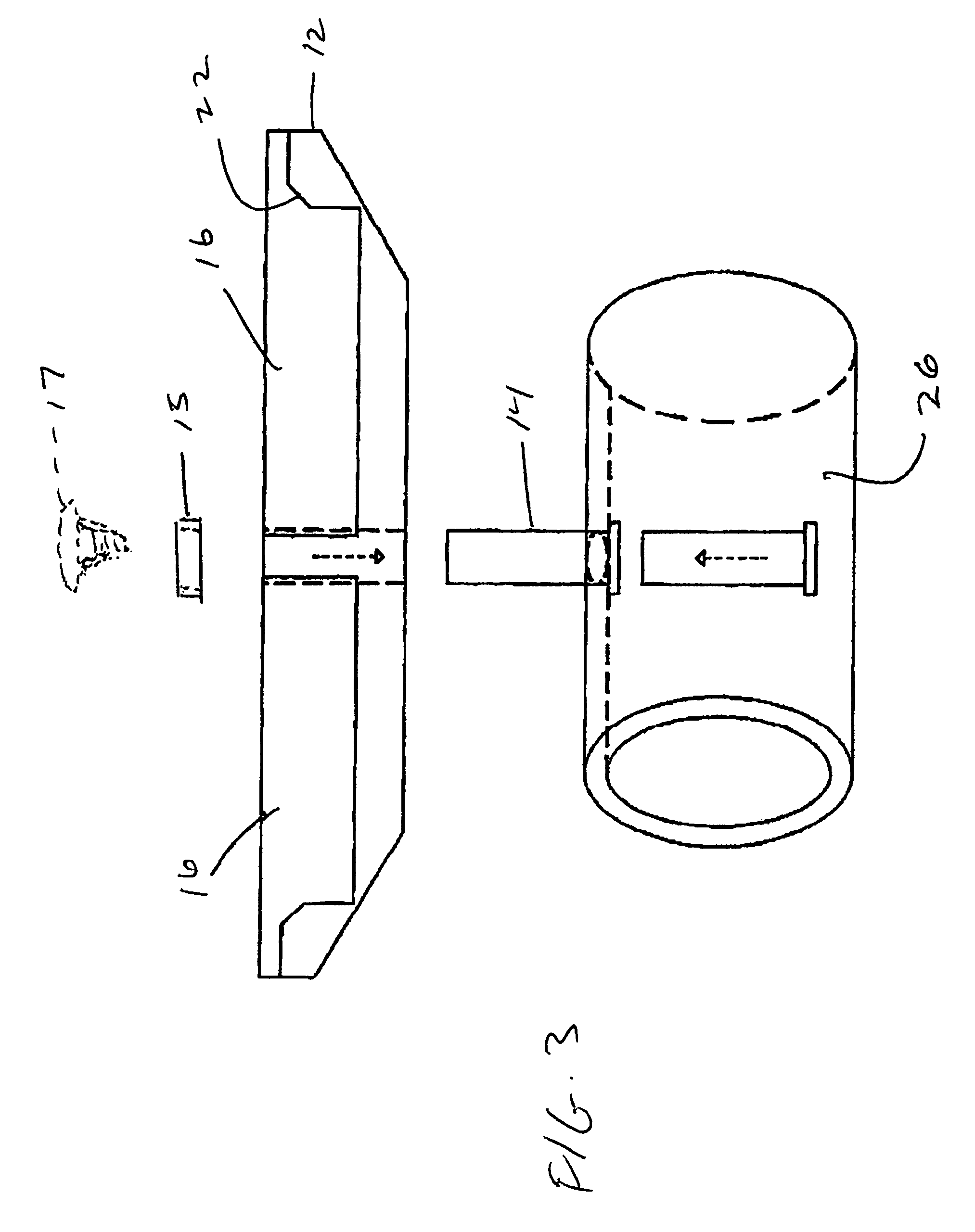
[0022]Referring first to FIGS. 1-5, there is provided a hair graft holder 10 comprising a tray 12 rotatably mounted on a base or pin 14. Tray 12 is rotatably mounted on base 14 and held in place by friction, or by use of e.g., an O-ring or C-ring or a malleable cap or nut shown generically at 15 fitted over the top end of the pin. Alternatively, the tray 12 may be rotatably mounted to the pin by a screw shown in phantom at 17 in FIG. 3, or the top of the pin may be flared, e.g., as shown at 19 in FIG. 3A. Preferably tray 12 is removable from pin 14. A tray 12 and pin 14 preferably are formed of a bio-compatible autoclavable or disposable material such as Teflon, polyethylene, or Delrin. Tray 12 is generally a square in overall plan and includes a plurality of compartments 16. An open channel or spout 18 communicates with each compartment 16 and extends to an outside corner 20 of the tray 12. As best seen in FIGS. 3 and 4, channels 18 are quite shallow compared to compartments 16 and...


PUM


Abstract

A tissue graft holder comprising a tray having a plurality of compartments for supporting tissue grafts and a hydrating solution, a channel connecting each compartment to an edge of the tray. The tray is rotatably mounted to a support which in turn is adapted for attachment to an appendage of a user. A dissecting cutting board to accommodate the graft trays and maintain tissue hydration during graft dissection.

Description

CROSS REFERENCE TO RELATED APPLICATION[0001]This application claims priority under 35 USC 119 from U.S. Provisional Patent Application Ser. No. 60 / 473,030, filed May 23, 2003.FIELD OF THE INVENTION[0002]This invention relates generally to the field of devices for use in dermatologic surgery and cosmetology. The invention has particular utility for use in connection with hair transplantation procedures and will be described in connection with such utility, although other utilities are contemplated.BACKGROUND OF THE INVENTION AND DESCRIPTION OF PRIOR ART[0003]State of the art surgery for cosmetic hair transplantation involves redistributing permanent hair follicles from the back and sides of the head, to areas of hair loss. The most cosmetic method involves placing small bundles of hair—as they naturally occur—in small, closely approximated incisions on the scalp. Experience has shown the scalp has excellent blood supply and can support the transfer of at least 2000 of these bundles i...

Claims


Application Information

Patent Timeline
Patent Type & Authority Patents(United States)
IPC IPC(8): A61B17/34
CPCA61B19/26A61B17/322A61B2017/00752A61B2017/00969A61B2017/3225A61B2019/261A61B90/50A61B90/53
Inventor KEENE, SHARON
Owner KEENE SHARON
Learn More