
Systems and Methods for Tuning Filters

a filter and tuning system technology, applied in waveguide type devices, automatic frequency control, line transmission details, etc., can solve the problems of limiting the tuning range of filters, tuning elements or screws can potentially affect the resonant frequencies of other resonators or inter-resonator couplings, and it is difficult to build an electric signal filter for wireless communication, etc., to achieve more freedom of design layout, reduce cost, and simplify the effect of structur

Inactive Publication Date: 2009-01-27
SUPERCONDUCTOR TECHNOLOGIES INC
View PDF16 Cites 21 Cited by
  • Summary
  • Abstract
  • Description
  • Claims
  • Application Information

AI Technical Summary

Benefits of technology

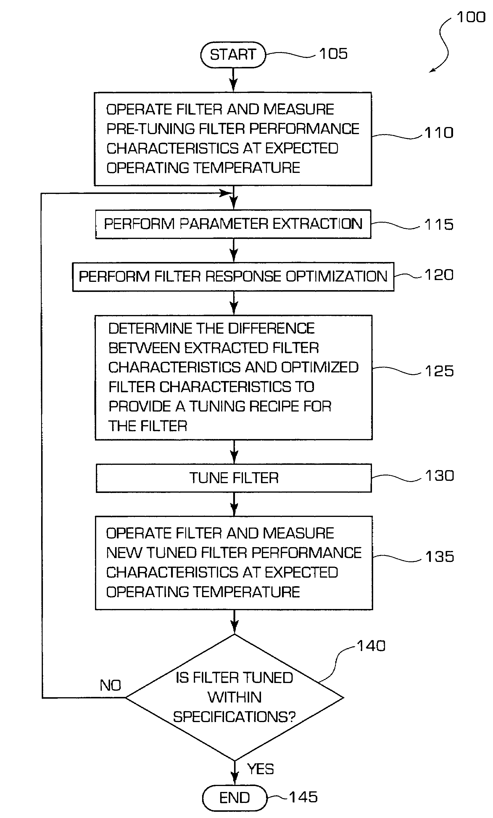
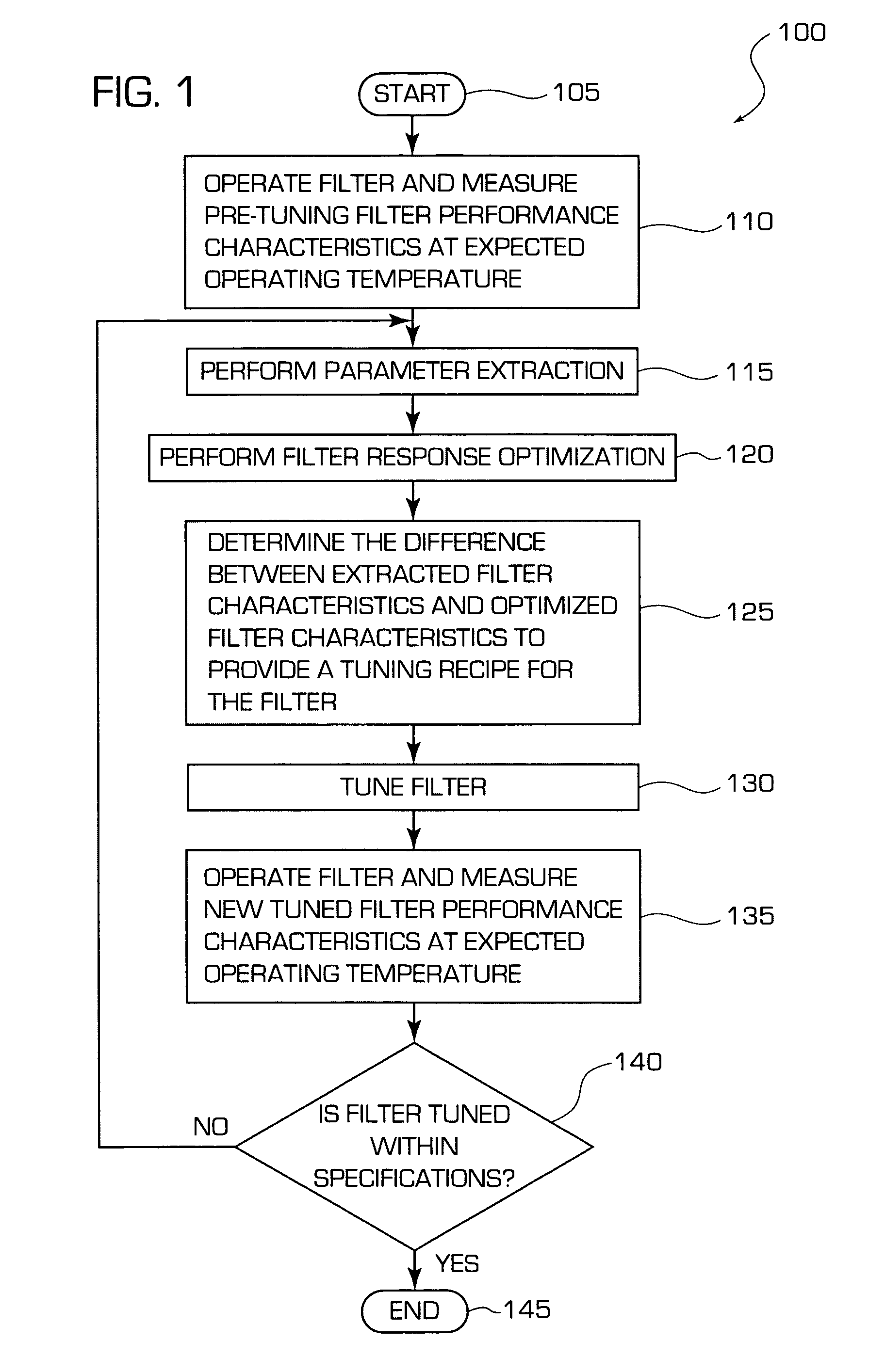
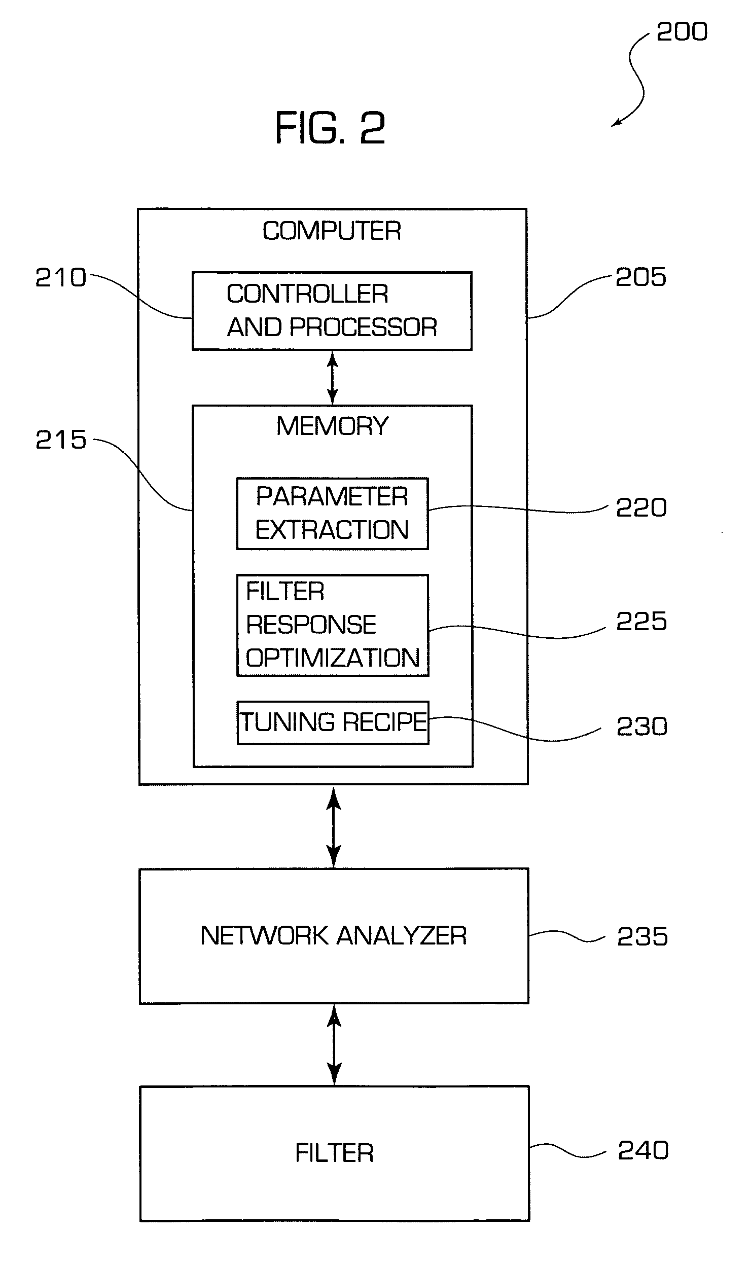
[0017]In at least one embodiment, the invention may include a design technique and filter design for high-performance planar filters. The technique provides one or more tuning elements that enable filter tuning by, for example, hand scribing, and a parameter extraction based technique to determine what should be scribed. In a multi-resonator planar filter, each resonator may have a tuning element, for example a tuning fork, that provides shunt capacitance to ground. The tuning fork may be coupled to the resonator by means of a series capacitor or connected directly to the resonator. However, sensitivity to error in scribing is decreased if the tuning fork(s) is connected directly to the resonator. The series capacitor can be designed to reduce the tuning sensitivity to approximately 10% of what would be seen if the tuning fork was directly connected to the resonator. This reduced sensitivity enables tuning by hand, e.g. with a mechanical device such as a diamond scribe pen. The hand scribing may be performed with a diamond scribe pen under a microscope. Alternate means of scribing the tuning fork, such as a laser scribing tool may also be employed. In any case, the resonator may be tuned by physically disconnecting (e.g., scribing) part of the tuning fork or shunt capacitor. For accuracy and ease of tuning, the tuning fork may also include a scale and / or numbering. Further, different capacitance tuning forks may be provided to give both course and fine tuning. A parameter extraction based technique may be used to diagnose the filter couplings and resonant frequencies, and to provide a recipe for scribing the tuning forks. As such, a filter design is provided that realizes very accurate tuning without requiring any expensive tools. However, in one variation, a laser trimming machine may be used to physically disconnecting a portion of the tuning fork or shunt capacitor.
[0022]Some of the advantages of the processing approaches provided herein are (1) filters that have simpler structure and lower cost because there are no mechanical parts required for tuning, (2) filters that are more reliable because the tuning is permanent, and (3) filters is more freedom of design layout due to the lack of mechanical tuning elements or screws that need to be taken into consideration during the design layout of planar filters.

Problems solved by technology

However, it is difficult to build an electric signal filter for wireless communication that has ability to discriminate between wanted and unwanted signals as well as desired.
However, substrate thickness variations and / or process variations such as etching conditions are likely to cause unacceptable resonant frequency variations of planar filters, and thus require tuning of planar filters.
One disadvantage of mechanical tuning is that the tuning elements or screws can potentially impact the resonant frequencies of other resonators or inter-resonator couplings when they are applied, especially when they are placed close to the circuit.
The variation in coupling ultimately limits the filter's tuning range.
This concern and approach limits freedom of design of planar filters.
There are other issues that may be caused by having mechanical part.
These flakes may affect the filter Q-factor and also change tuning as they are free to move around on the circuit.
However, there are two major issues that must be resolved in order to realize the second approach.
If the new performance characteristics are not acceptable, the filter may be tuned again or scrapped.
However, sensitivity to error in scribing is decreased if the tuning fork(s) is connected directly to the resonator.

Method used


Image

  • Systems and Methods for Tuning Filters
  • Systems and Methods for Tuning Filters
  • Systems and Methods for Tuning Filters

Examples


Embodiment Construction

[0047]The present invention is directed generally to filter design, analysis and adjustment. Various embodiments may include, for example, methods, systems and apparatus for electric filter tuning. Embodiments may also include design techniques for planar electric filter tuning. The methods, systems and apparatus of the present invention may be particularly well suited for tuning planar filters that may be used in RF and microwave applications. In various embodiments, the planar filters be made of, for example, a high temperature superconductor (HTS) materials such as YBa2Cu3O7-δ (YBCO). Embodiments of the present invention may also include parameter extraction, optimization and tuning recipes techniques. These techniques are not limited to applications with the filter designs used herein, such as trimming tab resonator and tuning fork resonator filter designs. These techniques may also applicable be applicable to mechanical tuning such as dielectric tuning filters and HTS tip tunin...


PUM


Abstract

Methods, systems and apparatus for filter design, analysis and adjustment are provided. Various embodiments may include, for example, methods, systems and apparatus for electric signal filter tuning. Embodiments may also include design techniques for planar electric signal (e.g., RF signals) filter tuning. In at least an embodiment of the present invention a technique for filter tuning is provided which may include parameter extraction, optimization and tuning recipes techniques that may require only a single permanent filter tuning. In at least another embodiment a system and method of filter design, analysis and adjustment according to the present invention includes use of tuning that may be set using a mechanical scribing tool or a laser trimming device. In at least one other embodiment, a filter tuning technique may be provided and include providing trimming tabs on a resonator edge that may be disconnected or trimmed for filter tuning.

Description

[0001]This application claims the benefit of U.S. Provisional Application No. 60 / 632,084, filed Nov. 30, 2004, the entire disclosure of which is hereby incorporated by reference as if set forth fully herein.STATEMENT OF GOVERNMENT INTEREST[0002]The invention provided herein was, at least in part, supported by the Totally Agile RF Sensor Systems, issued by DARPA / CMD under Contract No. MDA972-00-C-0010. The U.S. Government has a paid-up license in this invention and the right in limited circumstances to require the patent owner to license it to others on reasonable terms as provided for by the terms of Contract No. MDA972-00-C-0010 awarded by Defense Advanced Research Projects Agency, Defense Sciences Office, Order No. J607 (DARPA / CMD).BACKGROUND[0003]1. Field of the Invention[0004]The present invention relates to the field of filter analysis and design and, more specifically, to systems and methods relating to tuning filters.[0005]2. Description of Related Art[0006]The past few decad...

Claims


Application Information

Patent Timeline
Patent Type & Authority Patents(United States)
IPC IPC(8): H03J7/00
CPCH04B3/04
Inventor TSUZUKI, GENICHIHERNANDEZ, MATTHEW P.WILLEMSEN, BALAM A.
Owner SUPERCONDUCTOR TECHNOLOGIES INC
Learn More