Apparatus and method for resonant chemical and biological sensing

a chemical and biological sensing apparatus and resonant technology, applied in the field of environment sensing, can solve the problems of low finess, difficult to couple light into a multi-mode optical fiber, and reduce the round-trip reproducibility of the single fiber spatial mode within a multi-mod

Inactive Publication Date: 2009-01-27
HONEYWELL INT INC
View PDF17 Cites 22 Cited by
  • Summary
  • Abstract
  • Description
  • Claims
  • Application Information

AI Technical Summary

Problems solved by technology

Higher losses generally result in lower finesses.
It is generally difficult to couple light into a multi-mode optical fiber and maintain the light in a single spatial mode that reproduces itself for multiple circulations through the resonator.
For example, perturbations (e.g., imperfections, geometrical distortions, etc.) along the length of the optical fiber typically decrease the round-trip reproducibility of the single fiber spatial mode within a multi-mode fiber, and thus decrease the finesse.
Other spatial mode resonances can also be excited which typically cause errors in the intended measurement.
In the latter case, a complex structure of resonances, which may be based on a single stable resonance, may be observed that create instabilities and errors in the measurement.
Placing a permeable, chemically sensitive polymer cladding directly on the core of a typical single mode fiber is generally impractical because the core is too small (e.g., about 5-10 μm).
Such a small glass diameter typically lacks the mechanical strength normally associated with larger chemically sensitive multi-mode optical fibers.
Applying a relatively pliable cladding or coating around the core of a single mode optical fiber is also difficult in practice.
Adding an intermediate glass cladding between the core and a polymer coating would tend to interfere with sensing.

Method used


Image

  • Apparatus and method for resonant chemical and biological sensing
  • Apparatus and method for resonant chemical and biological sensing
  • Apparatus and method for resonant chemical and biological sensing

Examples


Embodiment Construction

[0016]The following detailed description of the invention is merely exemplary in nature and is not intended to limit the invention or the application and uses of the invention. Furthermore, there is no intention to be bound by any theory presented in the preceding background of the invention or the following detailed description of the invention.

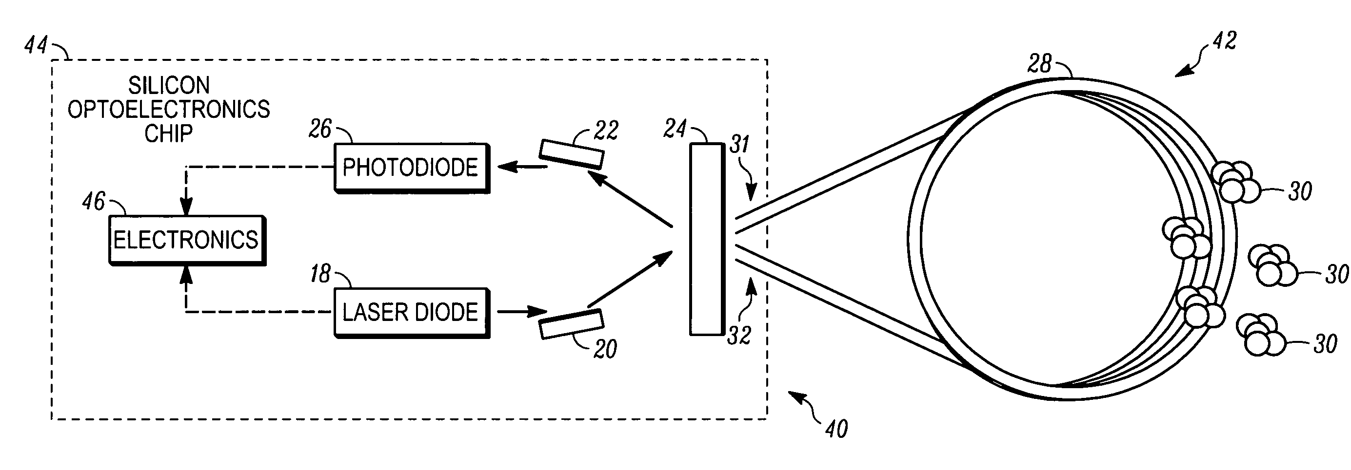
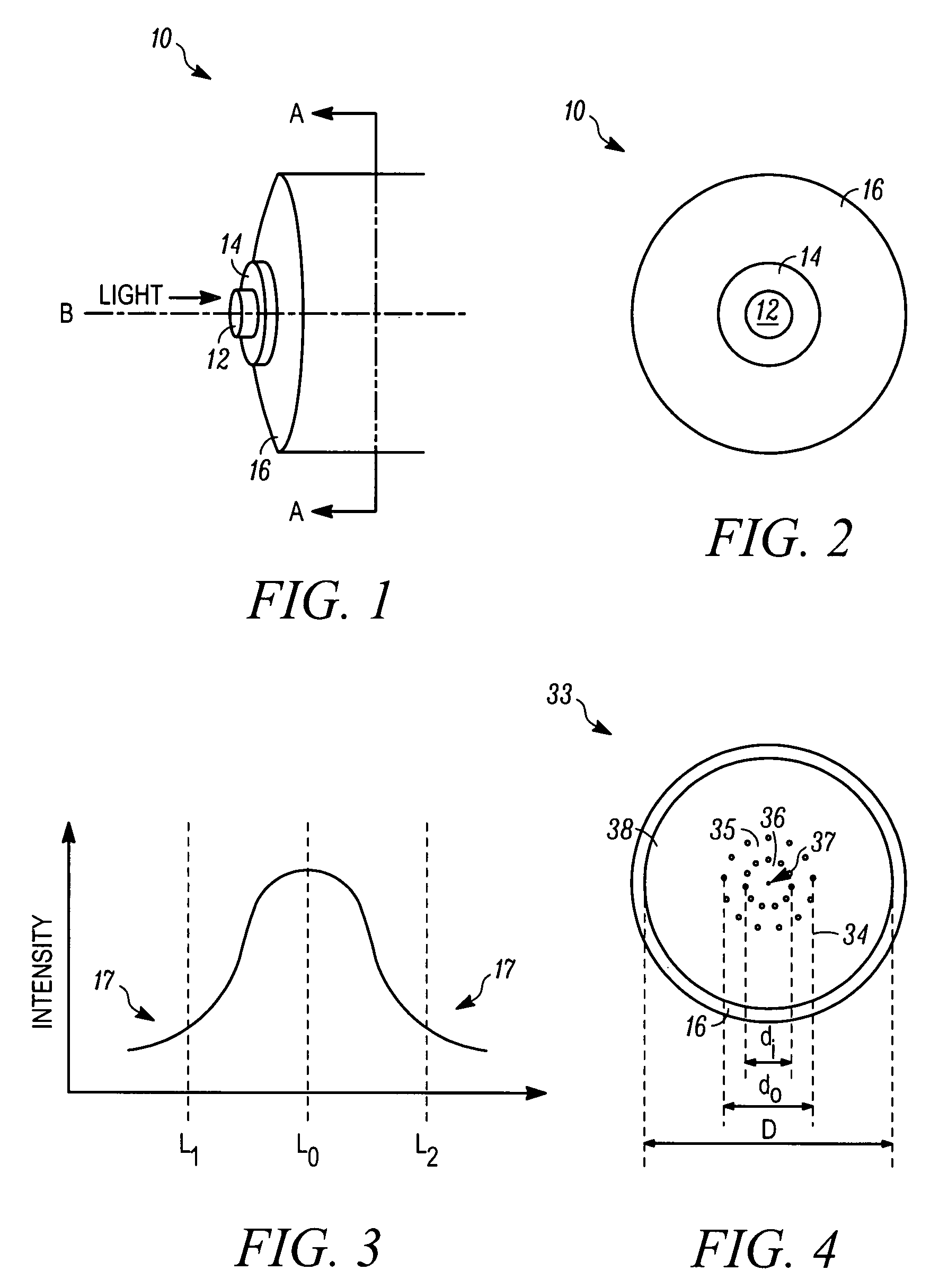
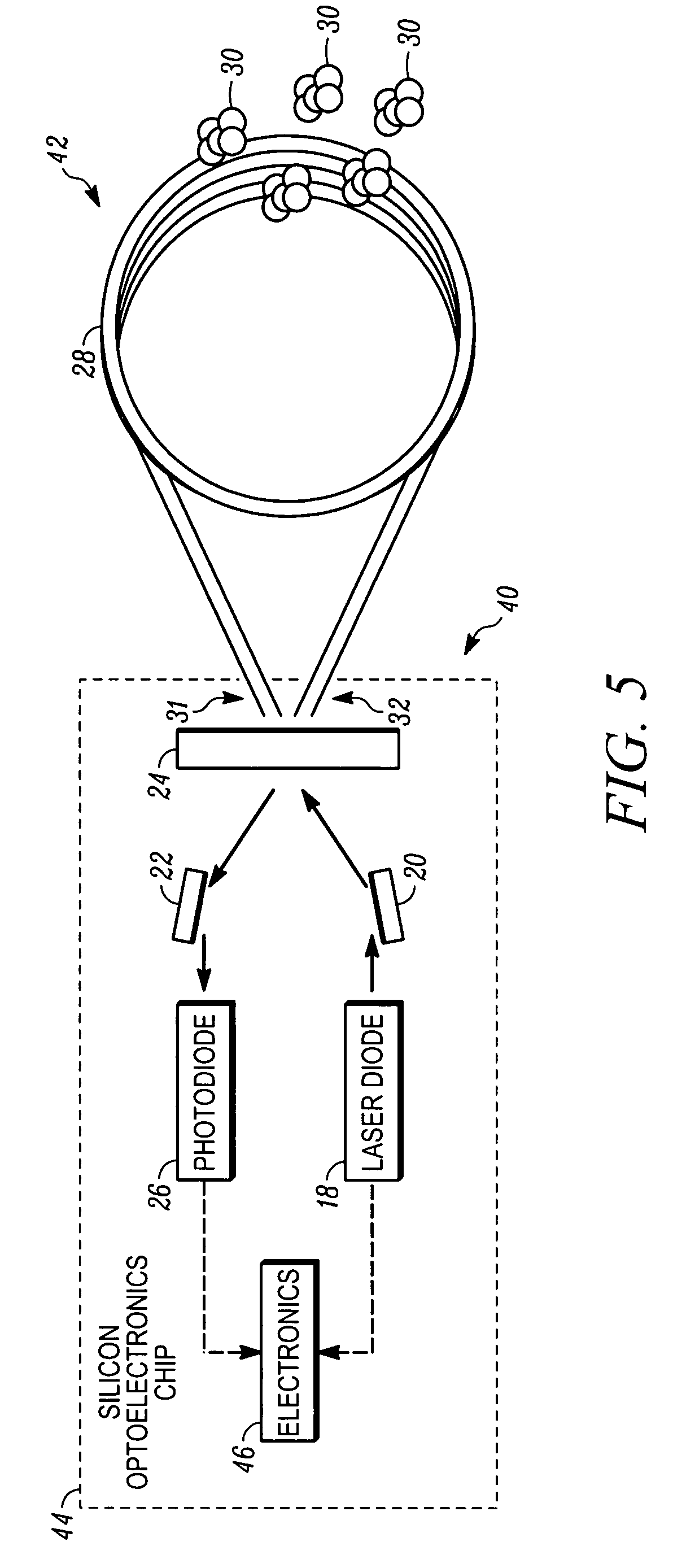
[0017]Apparatus and method are provided for sensing one or more chemical / biological agents in an environment. In general, the apparatus comprises a resonator having an optical fiber coil of photonic crystal fiber. The fiber is capable of guiding a substantially single optical mode of light that is spatially large (e.g., from about seven (7) to about thirty (30) times the wavelength of light supplied to the resonator) and includes, but is not necessarily limited to, a solid region for guiding the substantially single optical mode of light, a cladding with a photonic crystalline structure (e.g., a periodic hole structure) surrounding the solid...


PUM

PropertyMeasurementUnit
diameteraaaaaaaaaa
diameteraaaaaaaaaa
diameteraaaaaaaaaa

Abstract

Apparatus and method are provided for chemical and biological agent sensing. The sensing apparatus includes a resonator having a resonance frequency. The resonator includes a coil of a photonic crystal fiber. The photonic crystal fiber has a solid region configured to guide a substantially single optical mode of light having an evanescent tail, a first cladding surrounding an exterior of the solid region, and a polymer coating the first cladding. The polymer has an embedded indicator. The first cladding and polymer are together configured to extend a portion of the evanescent tail into the polymer. The resonator is configured to produce a resonance shape centered at the resonance frequency. A predetermined change in the resonance shape or the free spectral range indicates a reaction of the indicator to the agent.

Description

FIELD OF THE INVENTION[0001]The present invention generally relates to environment sensing, and more particularly relates to optical-based apparatus and methods for detecting the presence of a specific molecule.BACKGROUND OF THE INVENTION[0002]In recent times, greater emphasis has been placed on national home security and detecting threats to populations. In particular, detecting or sensing the presence of undesired chemicals or biological material in the environment has become a priority, and a variety of detection devices have been developed in response thereto. One possible implementation of a chemical sensor is a sensor using a multi-mode optical fiber having a glass core and a cladding surrounding the core. The cladding, or a coating on the cladding, has optical properties which are altered in the presence of a pre-determined material to be detected. As light is transmitted through the core of the optical fiber, the optical properties of the light vary with respect to changes i...

Claims


Application Information

Patent Timeline
Patent Type & Authority Patents(United States)
IPC IPC(8): G01B9/02G01N21/00G01N21/03G02B6/00
CPCG01N21/39G01N21/7746G02B6/02338G02B6/02342
Inventor SANDERS, GLEN A.
Owner HONEYWELL INT INC
Why Eureka
Try Eureka