System and method for power amplifier output power control

a power amplifier and output power technology, applied in gain control, high-frequency amplifiers, instruments, etc., can solve problems such as disadvantageous clipping of output power, failure of output frequency spectrum, and reduced power added efficiency

Active Publication Date: 2009-02-03
AXIOM MICRODEVICES
View PDF9 Cites 24 Cited by
  • Summary
  • Abstract
  • Description
  • Claims
  • Application Information

AI Technical Summary

Benefits of technology

[0016]The present invention provides many important technical advantages. One important technical advantage of the present invention is an architecture for detecting amplifier power which can avoid degraded performance under output load mismatch. By using the combined voltage and current detector, clipping and wind-up caused by load mismatch can be avoided. Furthermore, since the voltage and current are both being monitored, the power control loop can avoid over-voltage and over-current events caused by load mismatch.

Problems solved by technology

Furthermore, in such GSM systems, the amplifier may be required to have its output power ramped down to a low level at the end of the transmission burst.
If the shape deviates from the desired shape, particularly if sharp transitions occur, the output frequency spectrum may fail.
For instance, supply current sense and directional coupler power methods typically require inserting components in series with either the supply current or the output signal resulting in reduced power added efficiency, whereas supply voltage sense and output voltage sense do not typically have this disadvantage.
An issue that can arise in systems using power amplifier power control is that it is often desired to keep the amplifier output power in regulation at all times. For instance, in the GSM cellular standard, the transmission burst must meet a time mask requirement and a spectral frequency mask requirement, each of which can be difficult if the output power does not closely track the desired output power.
This clipping of the output power can be disadvantageous in multiple ways.
Additionally, sharp corner in the power versus time plot such as area 309 can cause failure to comply with the output frequency spectrum.
In addition to causing the output power to clip, requesting more power than the PA can produce can also cause a behavior known as wind-up.
This can occur when the feedback loop contains an integrator or other high gain device with limited bandwidth so that the error signal in the feedback loop causes the control loop to keep increasing even after the power amplifier ceases to make more output power with increasing control signal.
This can result in the control signal being much higher than the responsive range of the power amplifier when the desired output power is then reduced.
This can cause a delay between the requested reduction and the actual reduction in output power since the control loop must first reduce the control voltage to the useful range before the power can begin to reduce.
Because the output power is lower than the requested power, the integrated error signal in the control loop can grow large by the time that the ramp down begins.
Additionally, a sharp transition such as area 309 and high slope in region 411 can cause failure to comply with the output frequency spectrum.
These conditions can reduce the operating lifetime of the amplifier or even cause immediate destruction if not avoided.
Prior art power control systems that take measures to avoid these over-voltage and over-current conditions can be used to avoid this reliability issue, but these prior art power control systems add complexity and cost to the amplifier.
As a result, the higher current that can be caused by load mismatch is disadvantageous even if the amplifier reliability is not a concern.
Nevertheless, prior art systems are not effective at effectively eliminating power drain resulting from load mismatch.

Method used


Image

  • System and method for power amplifier output power control
  • System and method for power amplifier output power control
  • System and method for power amplifier output power control

Examples


Embodiment Construction

[0030]In the description which follows, like parts are marked throughout the specification and drawing with the same reference numerals, respectively. The drawing figures may not be to scale and certain components may be shown in generalized or schematic form and identified by commercial designations in the interest of clarity and conciseness.

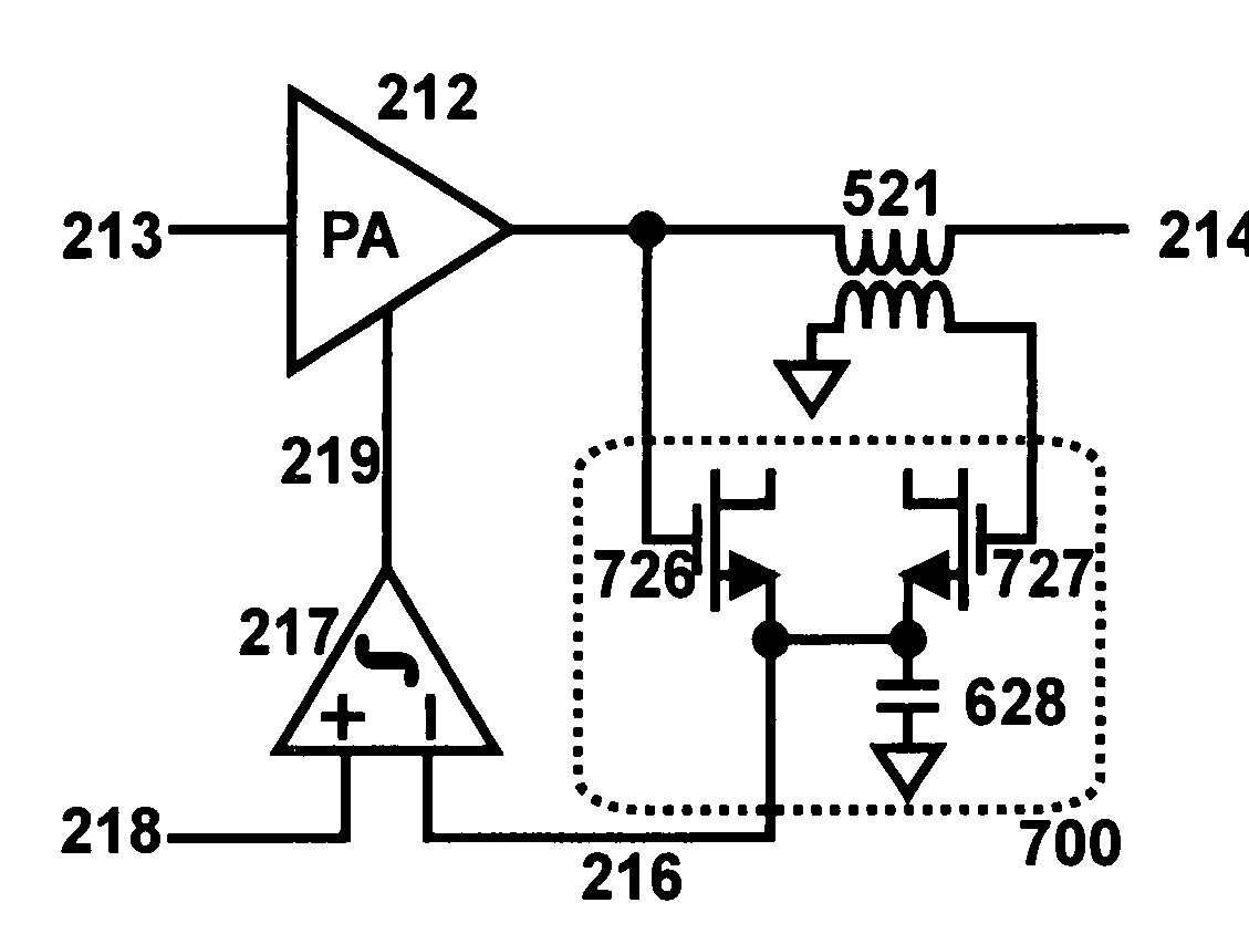
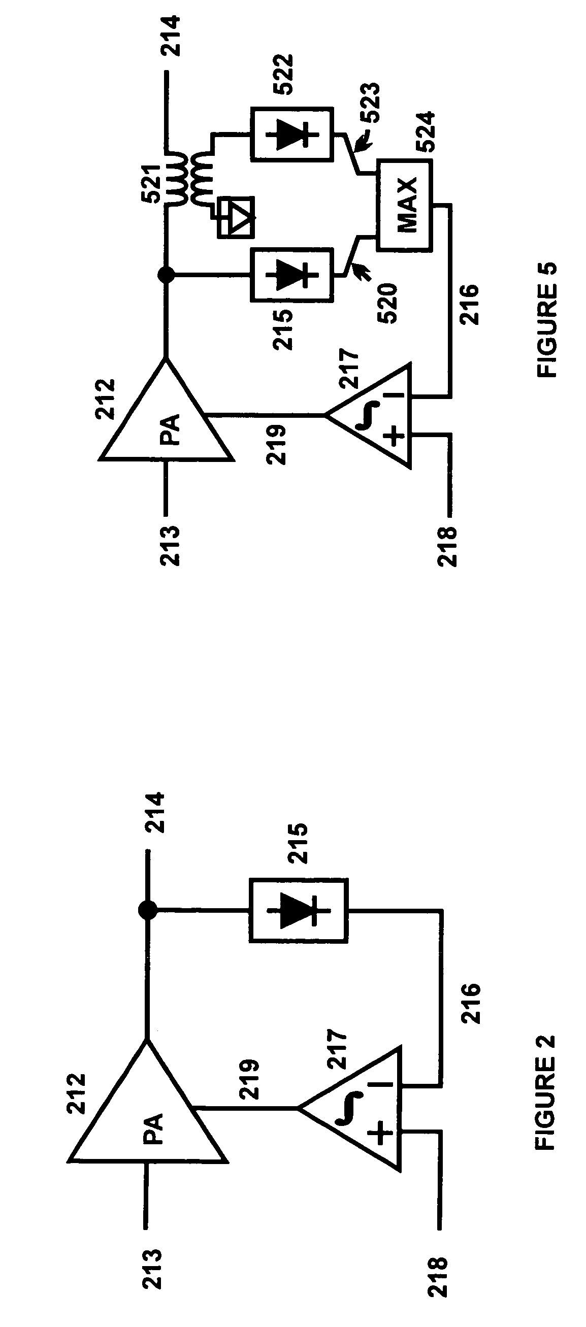
[0031]FIG. 5 is a diagram of power amplifier 212 and power control system 500 in accordance with an exemplary embodiment of the present invention. Power amplifier 212 and power control system 500 can be implemented in silicon, silicon germanium, gallium arsenide, or other suitable materials. Likewise, power amplifier 212 and power control system 500 can be implemented on a single integrated circuit, from discrete components, from a combination of integrated circuits and discrete components, or in other suitable manners.

[0032]Power amplifier 212 and power control system 500 can generate a signal 520 that is proportional to the rf voltage envelop...


PUM


Abstract

An architecture for detecting amplifier power is provided. The architecture includes a voltage envelope detector that receives a voltage signal and generates a voltage envelope signal. A current envelope detector receives a current signal and generates a current envelope signal. A power amplifier level controller receives the greater of the voltage envelope signal and the current envelope signal, such as by connecting the output of the voltage envelope detector and the current envelope detector at a common point and conducting the high frequency current components to ground via a capacitor. A power amplifier level control signal is then generated based on the voltage drop across the capacitor.

Description

RELATED APPLICATIONS[0001]The present application claims priority to U.S. Provisional Patent Application No. 60 / 843,191, filed Sep. 8, 2006 entitled “Architecture for Detecting Amplifier Power”; and is related to pending U.S. patent application Ser. No. 11 / 654,744, filed Jan. 18, 2007 and entitled “System and Method for Power Amplifier Output Power Control.”FIELD OF THE INVENTION[0002]The present invention relates generally to power control for use with power amplifiers, and more particularly to an architecture for detecting amplifier power.BACKGROUND OF THE INVENTION[0003]In many applications utilizing a power amplifier, it is desirable to control the amplifier's output power, so that the output power may be controlled independently of the input signal. For instance, in GSM cellular phones, the power amplifier may be required to have its output power ramped from a low level to the desired transmit power in a controlled manner at the beginning of a transmission burst. Furthermore, i...

Claims


Application Information

Patent Timeline
Patent Type & Authority Patents(United States)
IPC IPC(8): H03G3/20
CPCH03F1/02H03F1/52H03F3/19H03G3/3042H03G3/3047G01R21/12H03F2200/102H03F2200/451H03F2200/462H03F2200/471H03F2200/541H03F2200/99
Inventor MAGOON, RAHULAOKI, ICHIROLYU, JOHNKEE, SCOTTAPARICO JOO, ROBERTO
Owner AXIOM MICRODEVICES
Why Eureka
Try Eureka