Wide bandwidth, high power amplifier

a high-power amplifier and wide-band technology, applied in the field of radio frequency (rf) power amplifiers, can solve the problems of limited bandwidth of conventional power amplifier designs, inability to realize amplifier architectures, and inability to meet the requirements of amplifier architectures, etc., and achieve the effect of wide-band

Inactive Publication Date: 2009-02-03
TREX ENTERPRISES CORP
View PDF4 Cites 16 Cited by
  • Summary
  • Abstract
  • Description
  • Claims
  • Application Information

AI Technical Summary

Benefits of technology

[0017]The present invention provides a solid-state amplifier architecture which addresses both of the matching and impedance transformation issues, over a wide bandwidth. This invention also provides a solution to the problems of poor efficiency and harmonic termination. The invention provides an architecture that is superior to the circuits of the prior art, in terms of performance, manufacturability, reliability and cost. The present invention provides additional advantages over vacuum tube amplifiers, due to graceful degradation attribute of the amplifiers of the present invention.

Problems solved by technology

Power amplifiers are the most functional-restrictive and cost-inhibit element within a communication system.
Thus, conventional power amplifier designs often yield limited bandwidth.
However, these prior art amplifier architectures fall far short of realizing an amplifier architecture that can simultaneously achieve both very high output power (up to kilo-Watts) and extremely wide bandwidth (multi-octave or even decade).
Matching 0.5-Ohm to the system impedance of 50-Ohms at the ports, even over a modest bandwidth, is a significant challenge, if not impossible at times. Moreover, a corporate combiner must utilize several stages to accomplish the desired output power level.
Total insertion loss becomes very significant as the result and it is the key factor that curtails the use of corporate combiner in applications in which both wide bandwidth and high power are simultaneously required.
As shown in the simple example above, even when the reactive component of the device impedance is neglected and when only eight devices are combined, the performance of corporate combiners in high power applications is quite limited in terms of bandwidth and power.
There are two main difficulties here.
This leads to gross inefficiency as the number of devices to be used is large.
In power amplifier circuits, inefficiency leads to more difficult thermal management and ultimately poor reliability.
Again, this attribute of corporate-combined amplifiers is also not very desirable.
Also in wide band (for example, more than one octave) amplifiers, corporate power combine offers little defense against high harmonic contents especially when the second harmonic of an excitation tone falls within the bandwidth of interest.
This again is another undesirable attribute of conventional power amplifier design because of the fact that second harmonics are the main contributors to the creation of the menacing third-order inter-modulation products.
These inter-modulation products are very harmful to modern modulation schemes.
However, the prior art shows in FIG. 3 is still hampered by the matching and impedance transformation issues, by the insertion loss issue and by the inefficiency issue.
As can be seen, the TWT amplifier possesses many single points of failure.
The manufacturing and fine-tuning process for each TWT amplifier is very time consuming.
During storage, a strict and costly maintenance procedure must be carried out for TWTs.
Moreover, due to the slow wave structure (helix coil) being electrically long, TWT amplifiers possess poor gain ripple and group delay responses which are undesirable for a number of modem communication modulation schemes.
Furthermore, the power supplies associated with TWT amplifiers require very high voltages which are prone to various failure mechanisms.
Recently, there are efforts to produce TWT amplifiers using micro-fabrication techniques to address the issues of manufacturability, however, the critical issues of group delay variations and high voltage power supplies remain.
The problems with low reliability, poor serviceability, high gain ripples, non-constant group delay and DC power supply diminish the use of TWT in many critical applications.

Method used


Image

  • Wide bandwidth, high power amplifier
  • Wide bandwidth, high power amplifier
  • Wide bandwidth, high power amplifier

Examples


first preferred embodiment

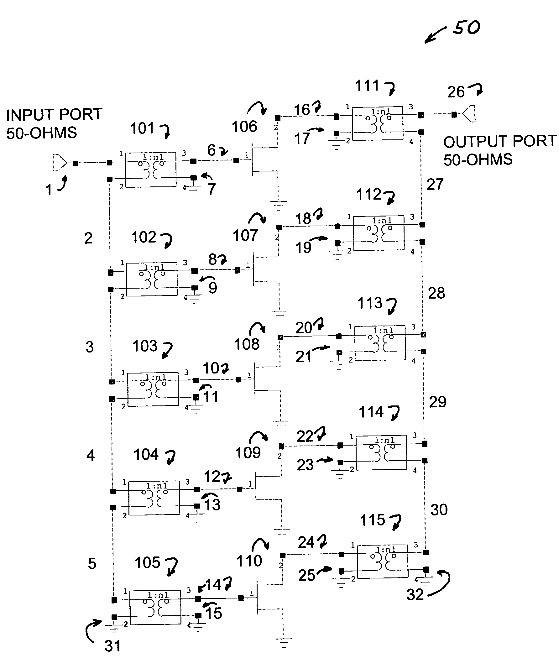
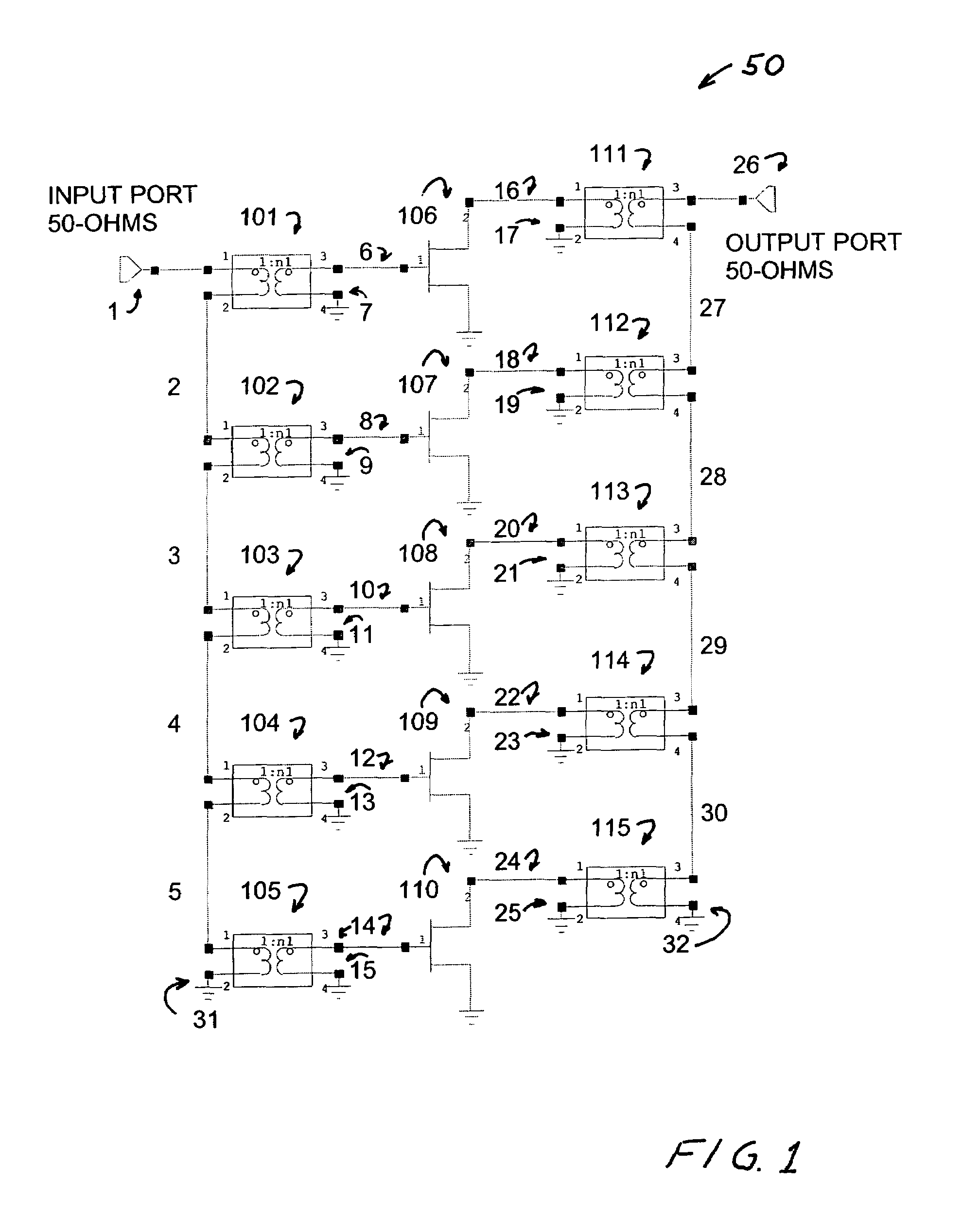
[0029]A preferred embodiment of the present invention is shown in FIG. 1. This embodiment provides a high power solid-state amplifier over a wide bandwidth. It is comprised of a series connection of 1:1 transformers to address the issues associated with impedance matching and impedance transformation typical in an amplifier design.

[0030]This embodiment provides a 1.0 kW amplifier system 50 matched in impedance to a standard 50-Ohm input port 1 and a 50-Ohm output port 26. The architecture of amplifier unit 50 provides the desired amplification with the impedance needed to match the input and output ports utilizing the special design techniques of the present invention. Applicants for this purpose utilize five 200W amplifier modules 106, 107, 108, 109 and 110. Each of these modules is comprised of five 50 Watt transistors (Part Number MRF9060) supplied by Motorola. Four of the five transistors are connected in series to provide the 200 Watt capacity and one of the five transistors is...


PUM


Abstract

A wide bandwidth, high power amplifier system for amplifying a signal in a radio frequency (RF) system in a specific bandwidth within the frequency range from 1 MHz to 100 GHz. The system includes a number of amplifier modules and an equal number of input transformers connected in series, with each input transformer providing an input signal to one amplifier module. It also includes an equal number of output transformers connected in series with each output transformer receiving an input signal from one amplifier module. The series of input transformers, the series of output transformers and the amplifier modules each provide an impedance matched approximately to the impedance of the RF system.

Description

CROSS REFERENCE TO RELATED APPLICATIONS[0001]This application claims the benefit of U.S. Provisional Application No. 60 / 752,582, filed Dec. 21, 2005.FEDERALLY SPONSORED RESEARCH[0002]This invention was made in the performance of a contract (Contract No. N68936-06-C-0051) with the Naval Air Systems Command (NAVAIR) and the United States Government has rights in the invention.BACKGROUND OF THE INVENTION[0003]1. Field of the Invention[0004]This invention relates to radio frequency (RF) power amplifiers and in particular to wide bandwidth and high power radio frequency amplifiers.[0005]2. Prior Art Solid State Power Amplifiers[0006]Power amplifiers are the most functional-restrictive and cost-inhibit element within a communication system. More often than not, the output power parameter is achieved at the expense of bandwidth. In other words, output power and bandwidth are two parameters to be traded-off in the design of conventional power amplifiers. The reason for such compromise is du...

Claims


Application Information

Patent Timeline
Patent Type & Authority Patents(United States)
IPC IPC(8): H03F3/26
CPCH03F3/19H03F3/211H03F3/265H03F2200/273H03F2200/451H03F2200/534H03F2200/537H03F2200/541H03F2203/21103H03F2203/21139
Inventor DO, KY-HEINSCHELLENBERG, JAMESMIYASHIRO, KEVIN
Owner TREX ENTERPRISES CORP
Why Eureka
Try Eureka