Coating for a mechanical part, comprising at least one hydrogenated amorphous carbon, and method of depositing one such coating

a technology mechanical parts, which is applied in the direction of superimposed coating process, chemical vapor deposition coating, coating, etc., can solve the problems of low thermal stability high intrinsic stress of hydrogenated amorphous carbon film, etc., and achieve good anti-wear and anti-friction properties.

Inactive Publication Date: 2009-02-10
COMMISSARIAT A LENERGIE ATOMIQUE ET AUX ENERGIES ALTERNATIVES
View PDF3 Cites 2 Cited by
  • Summary
  • Abstract
  • Description
  • Claims
  • Application Information

AI Technical Summary

Benefits of technology

[0009]It is an object of the invention to achieve a coating able to adhere perfectly to a mechanical part able to have any type of shape, able to be thermally stable at high temperatures, preferably greater than 250° C., and having, in particular, good anti-wear and anti-friction properties.
[0014]It is a further object of the invention to provide a method of depositing a coating for a mechanical part that is easy to implement, inexpensive and able to be performed at low temperature.

Problems solved by technology

However, the hydrogenated amorphous carbon film presents very high intrinsic stresses, of some several GPa.
As these high stresses may have an adverse effect on the adhesion of the film to a mechanical part, in particular a steel part, they do not enable depositions with a thickness of more than 5 micrometers to be performed.
Moreover, hydrogenated amorphous carbon has a relatively low thermal stability, which prevents a DLC coating being used for temperatures higher than 250° C. The friction coefficient of DLC also increases according to the humidity content in the atmosphere.
This type of coating is however not easy to implement, in particular for mechanical parts having a complex shape.
As the intrinsic stresses of hydrogenated amorphous carbon are high, coatings with a thickness larger than 5 micrometers are not able to be achieved, which may limit the performances of the coatings.
Furthermore, making a deposition of doped or non-doped hydrogenated amorphous carbon, or a deposition constituted by a composite material containing hydrogenated amorphous carbon, can not be performed at low temperature.
Implementation of such a deposition may also be long and costly to obtain anti-wear, anti-friction and thermal stability properties which may be not enough satisfactory in certain types of application.

Method used


Image

  • Coating for a mechanical part, comprising at least one hydrogenated amorphous carbon, and method of depositing one such coating
  • Coating for a mechanical part, comprising at least one hydrogenated amorphous carbon, and method of depositing one such coating

Examples


Embodiment Construction

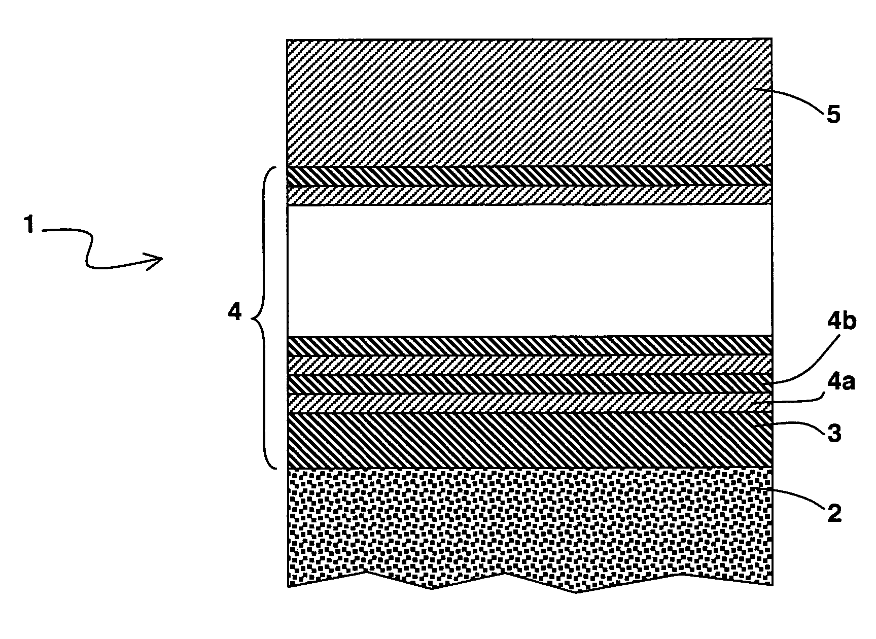
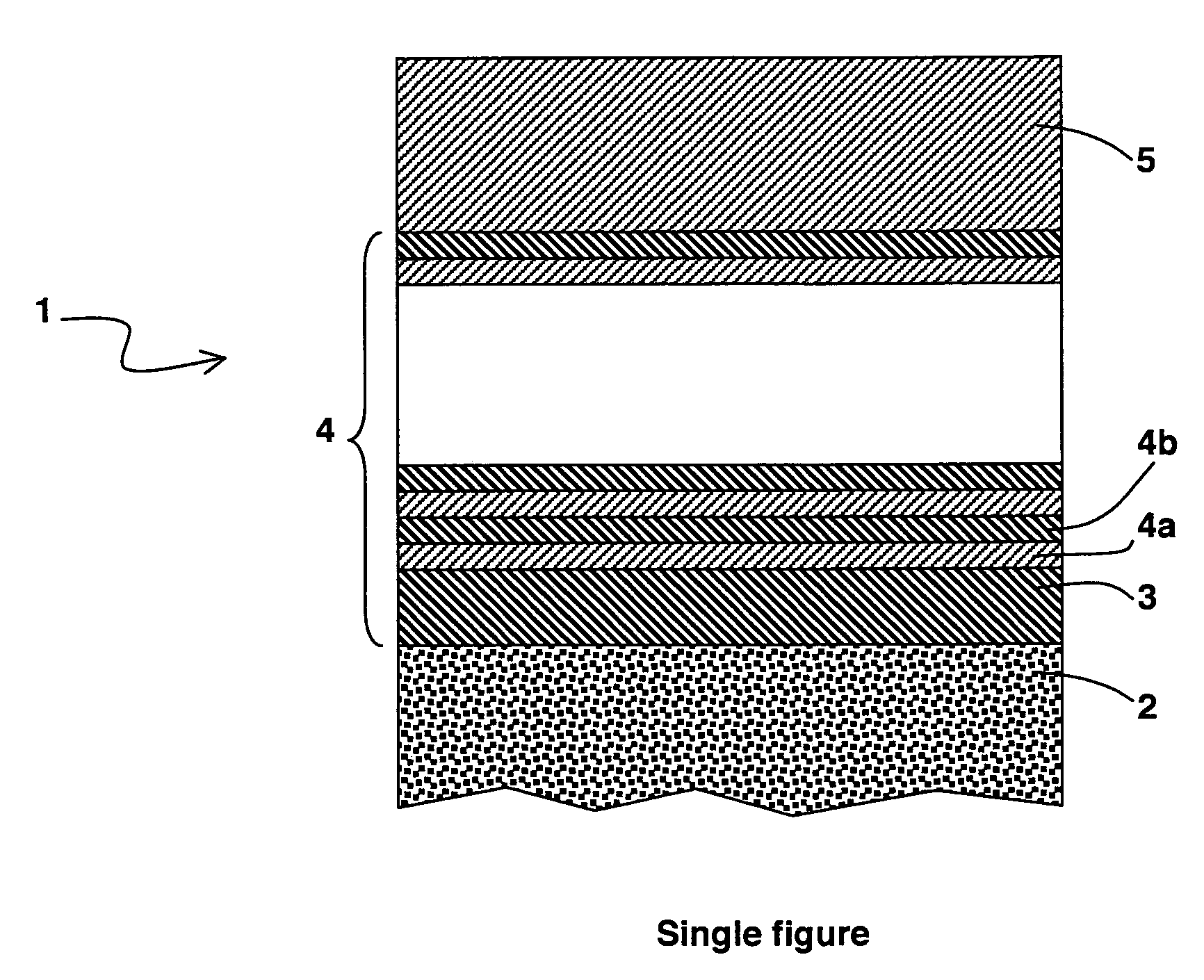
[0021]As represented in the single FIGURE, a coating 1, preferably having a total thickness comprised between 10 and 20 micrometers, is deposited on a mechanical part 2 so as to protect the surface of the part 2 against wear and against friction. The coating 1 comprises a first layer 3 of hydrogenated amorphous silicon carbide, a stack of layers 4 and an layer external 5 of hydrogenated amorphous carbon (DLC). The first layer 3 is arranged on the surface of the mechanical part 2 and preferably has a thickness comprised between 150 and 300 nanometers whereas the external layer 5 made from hydrogenated amorphous carbon has a thickness comprised between 0.5 and 2 micrometers. What is meant by hydrogenated amorphous silicon carbide, also noted SiC:H or a-Si1-xCx:H, x preferably being about 0.5, is an amorphous silicon carbide compound in which a smaller proportion of hydrogen than the proportions of silicon and carbon is incorporated. Such a compound does not comprise any C—C type bonds...


PUM

PropertyMeasurementUnit
thicknessaaaaaaaaaa
thicknessaaaaaaaaaa
thicknessaaaaaaaaaa

Abstract

A coating for a mechanical part comprises a first layer of hydrogenated amorphous silicon carbide designed to be in contact with the mechanical part, a stack of layers and an external layer of hydrogenated amorphous carbon. The stack is formed by an alternation of layers respectively of hydrogenated amorphous carbon and of hydrogenated amorphous silicon carbide. The coating has a total thickness preferably comprised between 10 and 20 micrometers.

Description

BACKGROUND OF THE INVENTION[0001]The invention relates to a coating for a mechanical part comprising at least one external layer of hydrogenated amorphous carbon.STATE OF THE ART[0002]To improve the resistance of mechanical parts to wear and friction, it is possible to coat them with a film of hydrogenated amorphous carbon, also called DLC (Diamond Like Carbon). Hydrogenated amorphous carbon does in fact present a very great hardness, a high Young's modulus, and the friction and wear coefficients are extremely low. In addition, the hydrogenated amorphous carbon film presents a small roughness and a low porosity and it has a low surface energy.[0003]However, the hydrogenated amorphous carbon film presents very high intrinsic stresses, of some several GPa. As these high stresses may have an adverse effect on the adhesion of the film to a mechanical part, in particular a steel part, they do not enable depositions with a thickness of more than 5 micrometers to be performed. Moreover, hy...

Claims


Application Information

Patent Timeline
Patent Type & Authority Patents(United States)
IPC IPC(8): B32B9/00C23C16/02C23C16/26
CPCC23C16/0272C23C16/26Y10T428/30C23C28/34C23C16/325
Inventor PLISSONNIER, MARCGAILLARD, FREDERICTHOLLON, STEPHANIE
Owner COMMISSARIAT A LENERGIE ATOMIQUE ET AUX ENERGIES ALTERNATIVES
Why Eureka
Try Eureka