DLL driver control circuit

a driver control circuit and driver technology, applied in the direction of automatic control, electrical equipment, etc., can solve the problems of unnecessarily consuming energy, increasing the increasing the amount of current consumption of drams, so as to reduce the operating current of drams

Active Publication Date: 2009-02-10
SK HYNIX INC
View PDF13 Cites 34 Cited by
  • Summary
  • Abstract
  • Description
  • Claims
  • Application Information

AI Technical Summary

Benefits of technology

[0009]It is, therefore, an object of the present invention to provide a DLL circuit capable of decreasing operating current of a DRAM by preventing DLL clocks from being toggled meaninglessly during any interval, limiting toggling to an interval during which they are actually used, in a normal mode as well as a power-down mode or a self refresh mode.
[0012]As described above, the present invention allows a DLL clock to be toggled only during a partial interval of an active mode when a signal associated with the active mode (read or write) is input in a state that the DLL driver is turned off.

Problems solved by technology

The more frequently output clocks are toggled, the higher amount of current consumption in the DRAM becomes.
This current consumption can amount to dozens of mA.
Consequently, the conventional DLL circuit generates clocks even when they are not used, thereby consuming energy unnecessarily.

Method used


Image

  • DLL driver control circuit
  • DLL driver control circuit
  • DLL driver control circuit

Examples


Embodiment Construction

[0023]Hereinafter, a preferred embodiment of the present invention will be set forth in detail with reference to the accompanying drawings so that the invention can be readily carried out by those in the art to which the invention pertains.

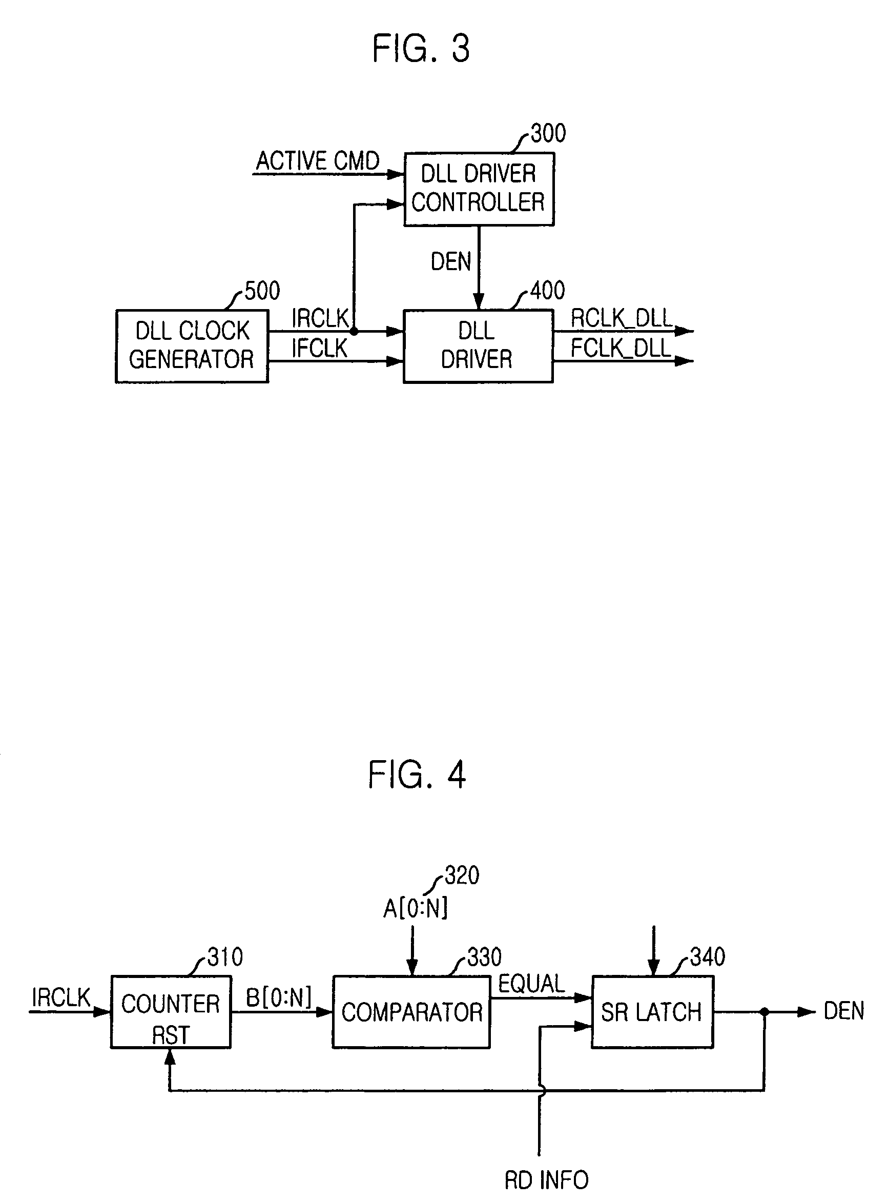
[0024]FIG. 3 is a block diagram of a DLL circuit in accordance with a preferred embodiment of the present invention.

[0025]As exemplified in FIG. 3, the inventive DLL circuit includes a DLL clock generator 500 having a clock buffer, a delay line, a phase comparator, a delay controller and a delay replica model and for generating DLL clocks irclk and ifclk synchronized with a phase of an external clock by performing phase update, a DLL driver 400 for driving the DLL clock signals irclk and ifclk, and a DLL driver controller 300 for controlling an operation of the DLL driver 400 in response to a signal having information associated with an active mode.

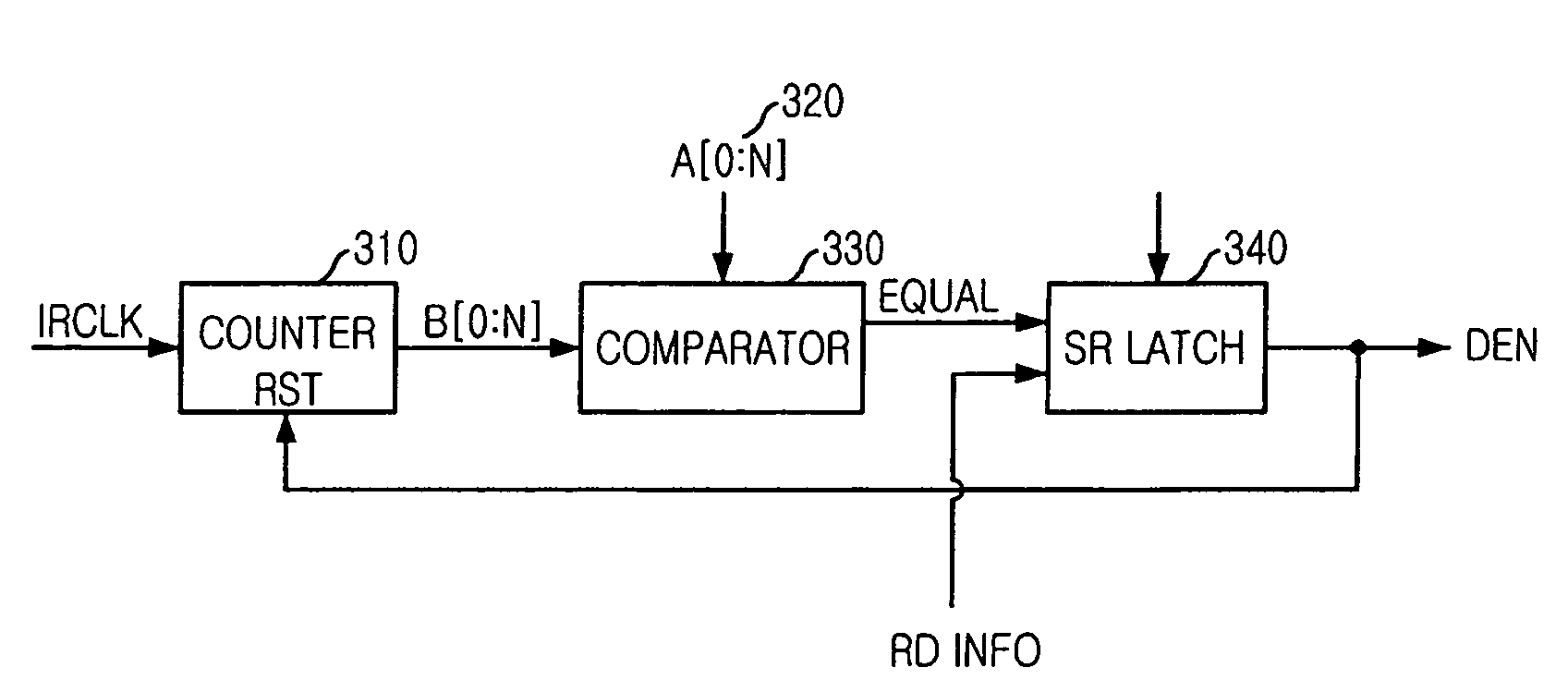
[0026]FIG. 4 exemplifies a detailed block diagram of the DLL driver controller 300 of the present in...


PUM


Abstract

A Delay Locked Loop (DLL) driver control circuit is capable of reducing an amount of current consumption by preventing the output of unnecessary clocks. The DLL driver control circuit includes a DLL driver for driving a DLL clock and a DLL driver controller for generating a control signal to control an operation of the DLL driver in response to a signal having information associated with an active mode. The DLL driver controller is provided with a counter for counting the DLL clock to produce a count a setting value having a plurality of bits and generating an activated equal signal if the two values are the same, and an SR latch for accepting the equal signal and the signal having the information associated with the active mode to provide the control signal.

Description

FIELD OF THE INVENTION[0001]The present invention relates to a semiconductor memory device; and, more particularly, to a Delay Locked Loop (DLL) driver control circuit capable of reducing an amount of current consumption by preventing the output of an unnecessary clock.DESCRIPTION OF RELATED ARTS[0002]A semiconductor memory device that operates at a high speed such as Double Data Rate Synchronous Dynamic Random Access Memory (DDR SDRAM) transmits data in synchronism with an external clock. For the high speed operation, it is necessary to establish clock synchronization. A DLL circuit is built in a semiconductor to control timing of data to be sent externally from DRAM depending on an external clock in order to synchronize the data with the clock. In other words, the DLL circuit serves to receive an external clock and output data based thereon.[0003]FIG. 1 is a block diagram of a conventional DLL circuit and FIG. 2 is a circuit diagram of the common DLL driver controller 100 shown in...

Claims


Application Information

Patent Timeline
Patent Type & Authority Patents(United States)
IPC IPC(8): H03L7/00H03L7/06
CPCH03L7/0805H03L7/0814H03L7/0816
Inventor KIM, KYUNG-HOON
Owner SK HYNIX INC
Why Eureka
Try Eureka