Process and apparatus for comminuting silicon

a technology of silicon granules and comminution equipment, which is applied in the direction of gas current separation, solid separation, grain milling, etc., can solve the problems of silicon loss, silicon loss, dust being entrained in the exhaust gas system, and the inability to be too small, so as to achieve a smaller flow cross section and low cost

Active Publication Date: 2009-02-17
WACKER CHEM GMBH
View PDF30 Cites 45 Cited by
  • Summary
  • Abstract
  • Description
  • Claims
  • Application Information

AI Technical Summary

Benefits of technology

[0023]It is an object of the present invention to provide an apparatus which makes it possible to produce silicon seed particles of a particle size of from 50 μm to 1000 μm from silicon granules with a particle size of from 300 μm to 5000 μm in an economic way, i.e. at low cost and in pure form. The average size of the product seed particles is lower than the average size of the starting granules. These and other objects are achieved by an apparatus comprising a vertically disposed jet chamber (8) with a preferably cylindrical cross section and having a jet nozzle (4) at the base of the jet chamber (8) through which a milling gas stream (1) can be introduced into the jet chamber (8); a countercurrent gravity separator (9) directly adjoining the jet chamber (8) and an inlet (6) for silicon granules (2), wherein the jet chamber (8) has a length which is sufficient to widen the milling gas stream to the cross section of the jet chamber, and the jet chamber (8) has a smaller cross section of flow than the countercurrent gravity separator (9). One embodiment of such an apparatus is illustrated in FIG. 2.

Problems solved by technology

Second, although the size of the silicon seed particles should be smaller than that of the silicon granules, it cannot be too small.
This is because particles which are too fine will be discharged from the fluidized bed with the exhaust gas stream and are therefore unsuitable for use as silicon seed particles.
A fines fraction in the silicon seed particles below this limit leads to silicon losses and to dust being entrained in the exhaust gas systems from the fluidized bed deposition.
Hitherto, it has often been impossible, or at least very difficult and / or expensive to obtain corresponding grain size distributions directly from the fluidized bed deposition or by classification from the product of the fluidized bed deposition.
Both processes have the drawbacks of extremely high energy consumption which is necessary to heat the fluidized bed, and silicon seed particle grain size distribution and production rate which are very difficult to control.
One drawback is that the size of the nuclei is in the nanometer range, and even agglomeration effects can only produce silicon seed particles of a few micrometers.
The silicon-silicon material pairing between roll and material being milled, however, leads to considerable wear to the layer of silicon on the rolls, and consequently only short machine campaigns are possible before the rolls have to be replaced.
A disadvantage of designs of this type is that it is almost impossible to produce a contamination-free or low-contamination material.
Considerable contamination of the milled product is likely.
However, as has already been mentioned in connection with the roll crushing process, the silicon-silicon material pairing leads to considerable wear to the obstacle.
However, the authors mention only a low yield, and consequently the silicon granules have to be milled a number of times.
An advantage of this process is that there is no need for any silicon granules to be removed from the deposition reactor, milled and returned, but a disadvantage is that in this case too, the production rate and the resulting grain size distribution of the silicon seed particles are difficult to control.
Moreover, the gas jet may have an adverse effect on the deposition process in the fluidized bed.
Accordingly, increasing the introduction of energy into the milling chamber by means of a higher gas throughput increases the separation grain size, and therefore also the upper limit, and consequently also the mean grain size of the comminuted particles which are discharged from the milling chamber.
The main drawback of conventional jet mills for the production of silicon seed particles is the fact that the optimum working range of these prior art apparatuses is at milled product grain sizes of approx.
The larger the grain size of feed material and milled product becomes, the less efficiently the mill operates; the specific gas consumption becomes greater and the process correspondingly less economical.
Nevertheless, the milling performance which can be achieved with this arrangement remains very low and is associated with a high specific energy and / or gas consumption.
Moreover, the space-time yield is very low.
According to this document, an increase in the solids concentration leads to a further drop in the milling performance.

Method used


Image

  • Process and apparatus for comminuting silicon
  • Process and apparatus for comminuting silicon
  • Process and apparatus for comminuting silicon

Examples


example 1

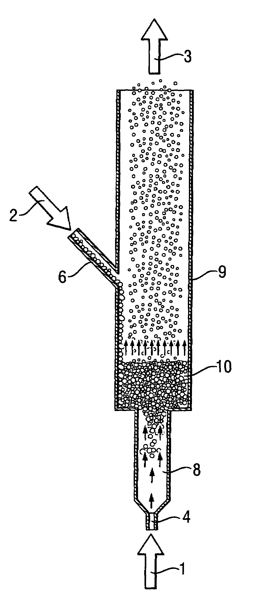
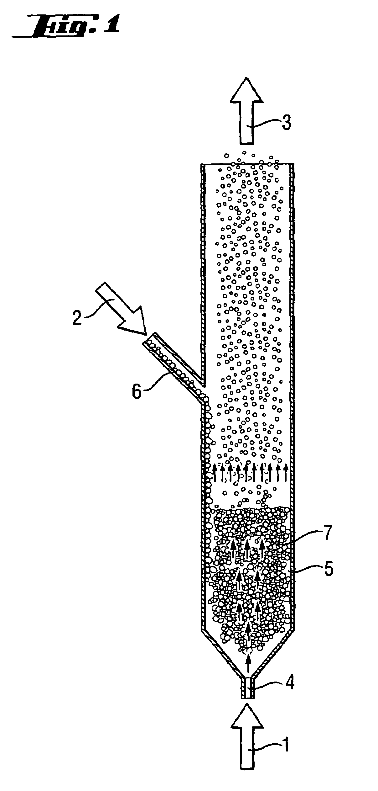
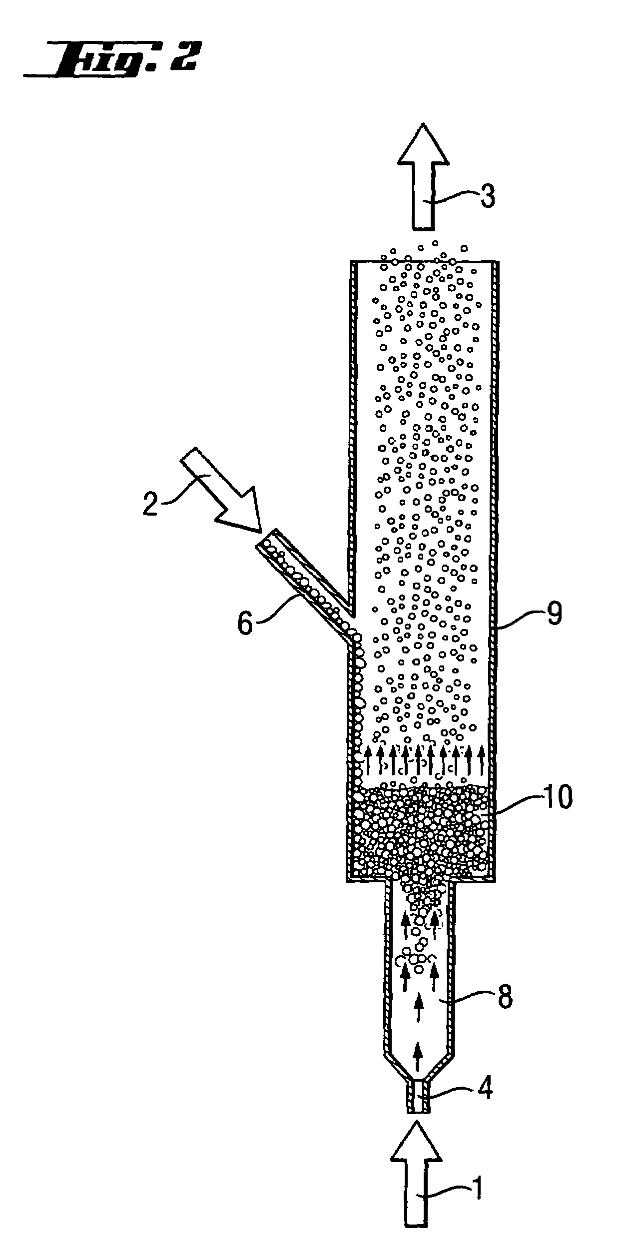
[0074]High-purity silicon granules were comminuted in a milling installation as illustrated in FIG. 3. The purpose of the milling was to produce silicon seed particles with a grain size distribution of between approximately 150 μm and 500 μm, the mean diameter (mass-referenced) of which was to be between 300 μm and 400 μm, from silicon granules with a grain size distribution between 250 μm and 4000 μm, with a mean diameter (mass-referenced) of 711 μm.

[0075]The flow cross section of the jet chamber was 3020 mm2, the flow cross section of the first zigzag separator was 4200 mm2 and the flow cross section of the second zigzag separator was 19,600 mm2. The milling flow nozzle, a Laval nozzle, had a narrowest circular cross section with a diameter of 4 mm. The jet chamber had a length of 550 mm.

[0076]The milling installation was operated for 14.5 hours. The mean metering of the feed material was in this case 17.83 kg / h. The Laval nozzle was used to set a milling gas flow of 52 m3 / h (s.t....


PUM


Abstract

An apparatus for producing silicon seed particles having a size of from 50 μm to 1000 μm from silicon granules having a size of from 300 μm to 5000 μm, comprising a vertically disposed jet chamber with a low cross sectional area and a jet nozzle at the base of the jet chamber through which a milling gas stream is introduced into the chamber; a larger cross section countercurrent gravity separator adjoining the jet chamber, and an inlet for silicon granules, wherein the jet chamber has a length sufficient to allow the milling gas stream to widen to the cross section of the jet chamber.

Description

BACKGROUND OF THE INVENTION[0001]1. Field of the Invention[0002]The invention relates to a process and an apparatus for comminuting silicon granules.[0003]2. Background Art[0004]Fluidized bed deposition processes for the production of high-purity silicon granules for the electronics industry or the photovoltaics industry have been described and disclosed in numerous publications. In these processes, silicon particles in a fluidized bed reactor are fluidized by gas and heated to high temperatures. Introducing a silicon-containing gas into the fluidized bed (e.g. silane, tetrachlorosilane or trichlorosilane) leads to a pyrolysis reaction at the particle surface, with elemental silicon being deposited on the particle surface, leading to particle growth. For continuous operation of these processes, relatively large “grown” particles have to be extracted from the fluidized bed as product, and fine particles, known as silicon seed particles, have to be supplied on an ongoing basis. A proc...

Claims


Application Information

Patent Timeline
Patent Type & Authority Patents(United States)
IPC IPC(8): B02C19/06
CPCB02C19/068B02C23/14C01B33/02
Inventor WEIDHAUS, DIETER
Owner WACKER CHEM GMBH
Why Eureka
Try Eureka