
Measuring methods for ion cyclotron resonance mass spectrometers

a mass spectrometer and cyclotron technology, applied in mass spectrometers, instruments, separation processes, etc., can solve the problems of reducing the usable volume of the measuring cell, the electric field outside the axis of the measuring cell is more complicated, and the frequency shift of the cyclotron frequency, so as to facilitate the detection of image currents

Active Publication Date: 2009-02-24
BRUKER DALTONIK GMBH & CO KG
View PDF31 Cites 25 Cited by
  • Summary
  • Abstract
  • Description
  • Claims
  • Application Information

AI Technical Summary

Benefits of technology

This approach reduces magnetron motion, maintains ion cloud stability, and enhances mass accuracy by allowing closer ion cloud proximity to detection electrodes, thereby increasing the measurement period and reducing space charge effects.

Problems solved by technology

The electric field outside the axis of the measuring cell is more complicated.
The superimposition of magnetron and cyclotron circular motion is an undesirable phenomenon which leads to a frequency shift in the cyclotron frequency.
Furthermore, it leads to a reduction in the usable volume of the measuring cell.
The loss of phase homogeneity leads to a reduction in the image currents and to a continuous decrease in the signal-to-noise-ratio, which reduces the usable measuring period.
Apart from the vacuum, the space charge in the ion cloud can also adversely affect the measurement.
The Coulomb repulsion between the ions themselves and, above all, the elastic reflection of the ions moving in the cloud lead to a large number of disturbances, which also result in an expansion of the cloud.
In present-day instruments, the space charge, alongside the effects of pressure, represents the greatest limitation on achieving high mass accuracy.
Unfortunately, these experiments have had such limited success that they have regularly been abandoned.
It can be assumed that the ion clouds do not hold together well enough and that, for this reason, they cannot be brought close enough to the detection electrodes.
Narrow electrodes require that the ion clouds are brought very close, as otherwise it is scarcely possible to induce the full image currents.
Integration over time results in a repulsion.
Furthermore, the space charge only allows the diameter of the ion string to increase very slowly.
Unfortunately, it cannot be eliminated completely, however.
However, since the RF voltages of the trapping electrodes lie between 10 and 100 volts, but the image voltages are only in the range of microvolts or less, this filtering is difficult.
Moreover, it appears that overtones, ripple voltages and interferences repeatedly result in frequencies in the range of the image currents, making measurement difficult.

Method used


Image

  • Measuring methods for ion cyclotron resonance mass spectrometers
  • Measuring methods for ion cyclotron resonance mass spectrometers
  • Measuring methods for ion cyclotron resonance mass spectrometers

Examples


Embodiment Construction

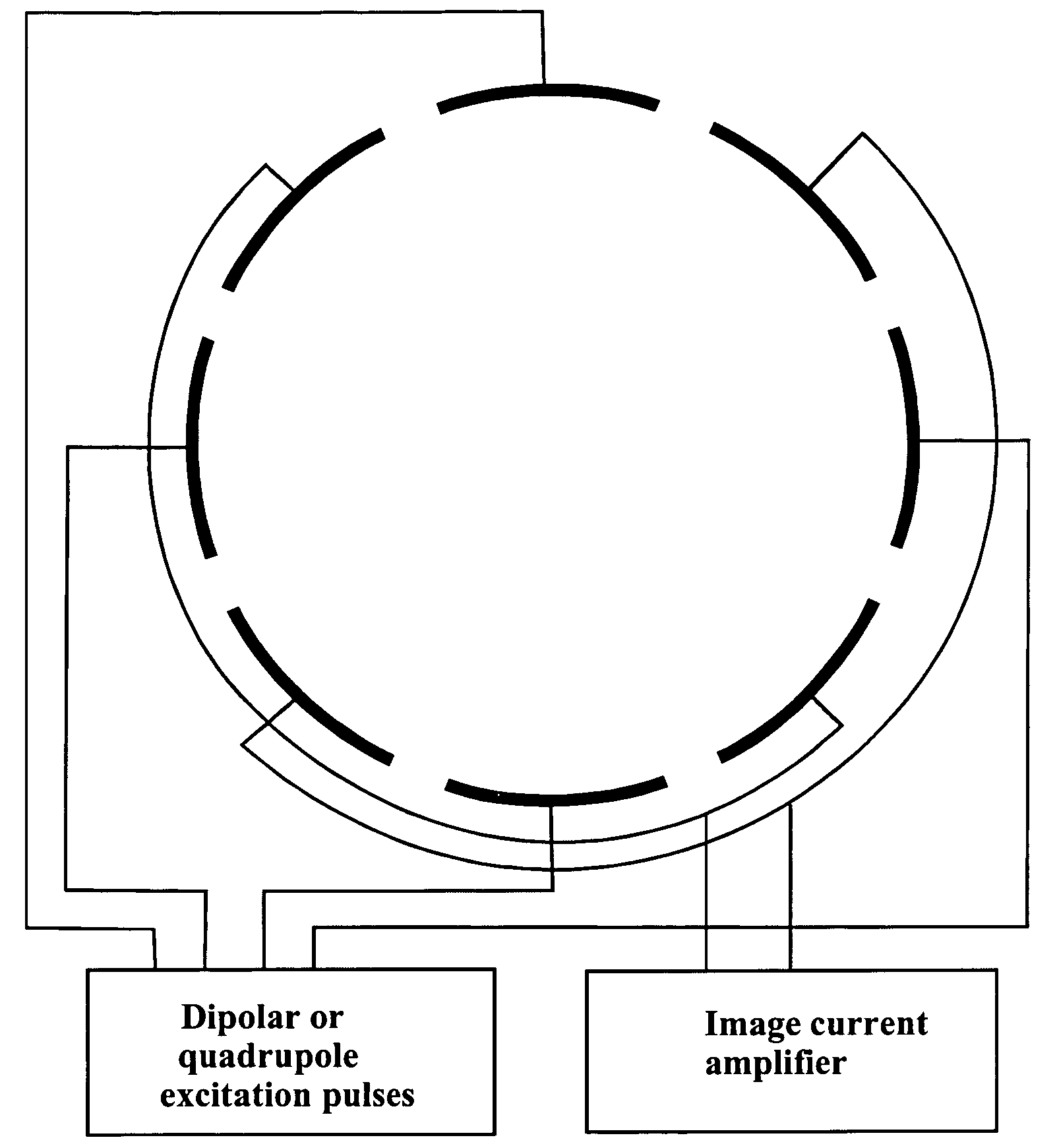
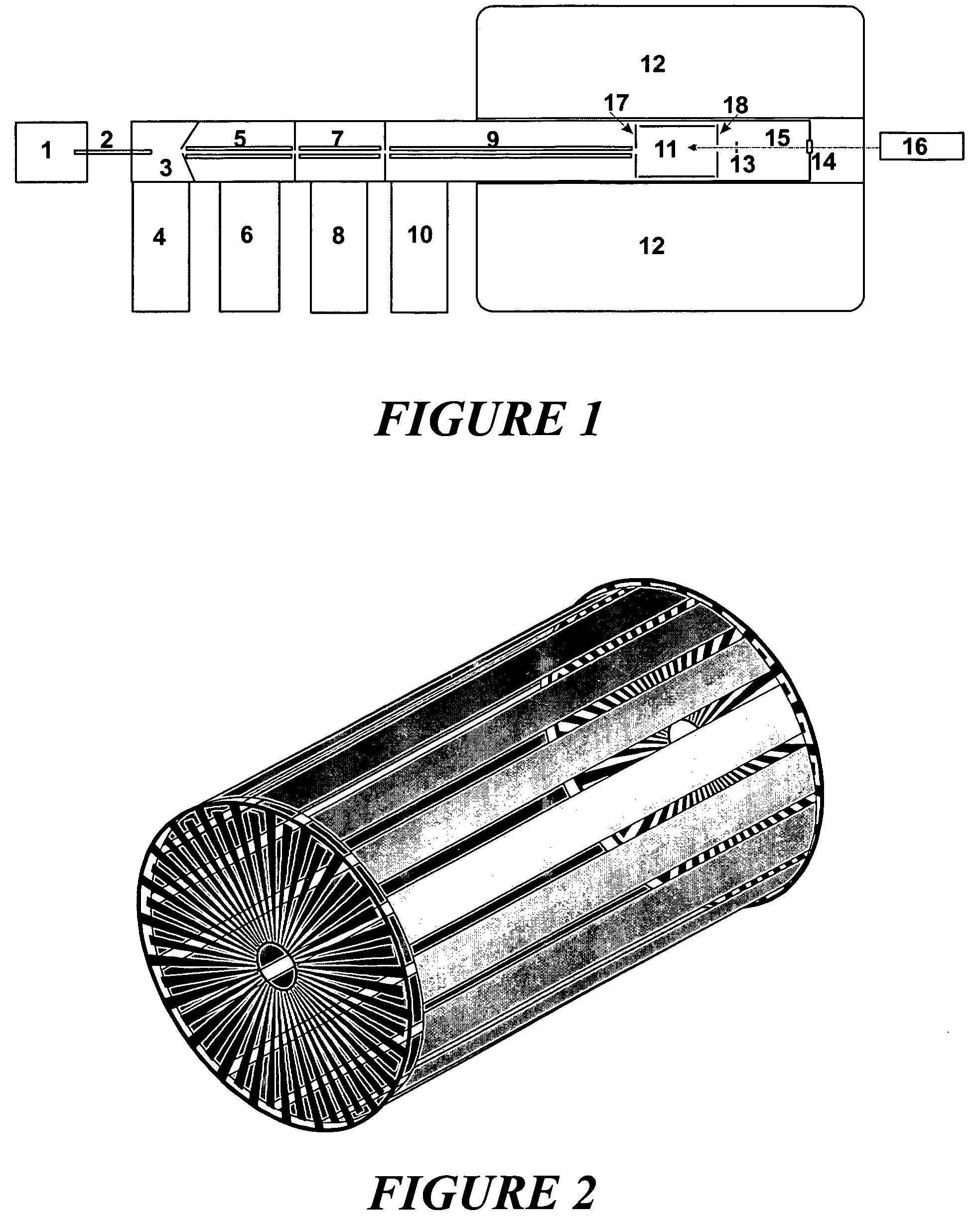
[0041]The operation and function of an ion cyclotron resonance mass spectrometer can be explained in greater detail using FIG. 1. The ions are, for example, generated by electrospray ionization in an out-of-vacuum ion source (1), and introduced together with ambient gas through a capillary (2) into the first stage (3) of a differential pump system, which comprises the chambers (3), (5), (7) and (9) and is evacuated by the pumps (4), (6), (8) and (10). The ions are captured by the ion guides (5), (7) and (9) and guided to the measuring cell (11), where they are confined. The measuring cell (11) usually comprises four longitudinal excitation and detection electrodes and two trapping electrodes (17) and (18), each of which has a central aperture. The measuring cell is located in the homogeneous region of a strong magnetic field, which is generated by superconductive coils in a helium cryostat (12) and has a magnetic field strength of high constancy. Electrons can be generated by a ther...


PUM


Abstract

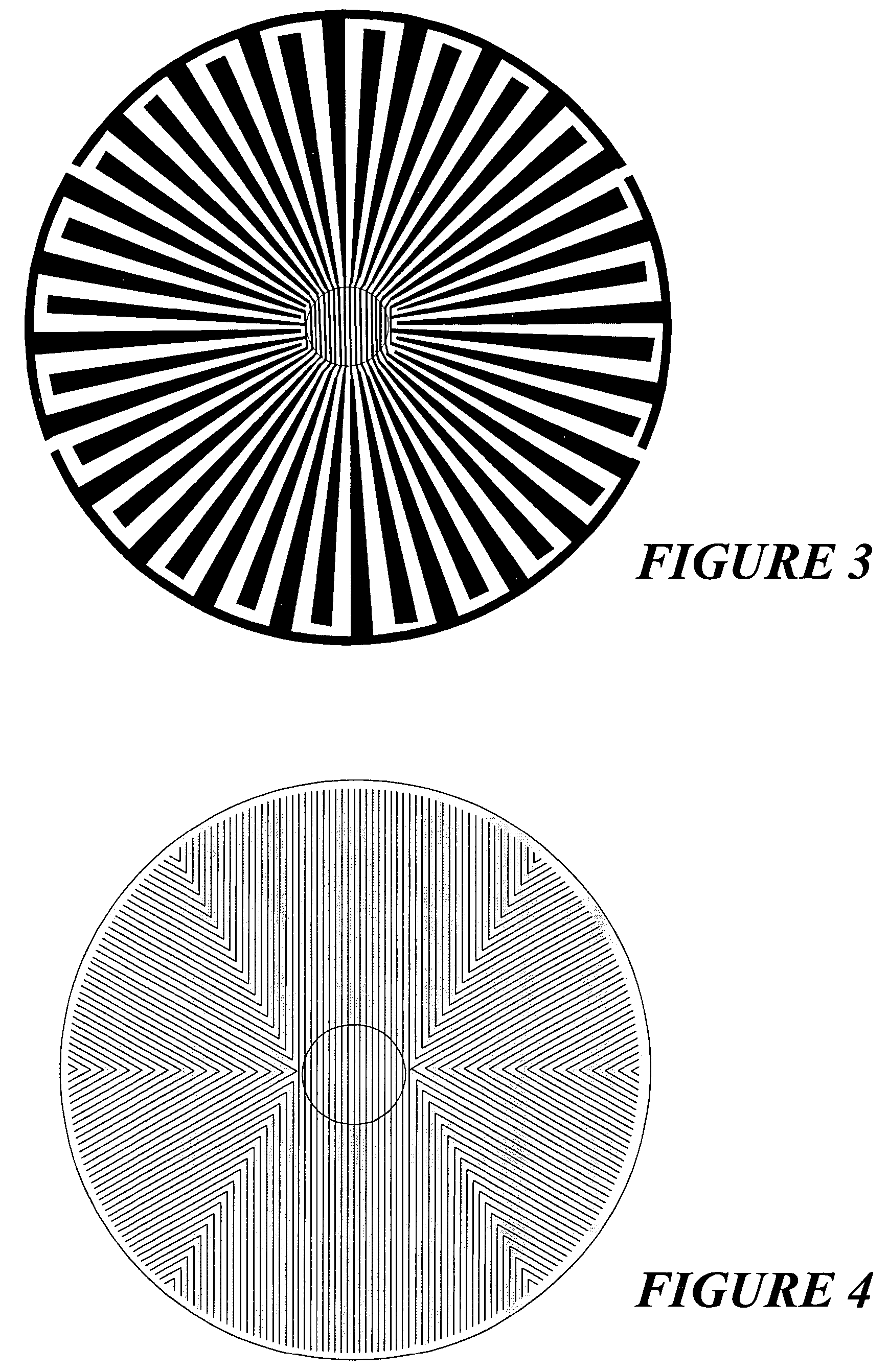
The invention relates to measuring methods and corresponding measuring cells for ion cyclotron resonance mass spectrometers (FTMS). The invention provides measuring methods with measuring cells, the ends of which each incorporate a large number of trapping electrodes, DC voltages of opposite polarities being applied across adjacent electrodes. For orbiting ions this builds up a repelling pseudopotential, which holds the ions in the measuring cell by reflection. This facilitates measurement of the image currents without the disturbing influence of RF voltages.

Description

FIELD OF THE INVENTION[0001]The invention relates to measuring methods and corresponding measuring cells for ion cyclotron resonance mass spectrometers (FTMS).BACKGROUND OF THE INVENTION[0002]In ion cyclotron resonance mass spectrometers (ICR-MS), the mass-to-charge ratios m / z of ions are measured by their cyclotron motions in a homogeneous magnetic field with high field strength. The magnetic field is usually generated by superconductive magnetic coils cooled with liquid helium. Nowadays they provide usable cell diameters of around 6 to 12 centimeters at magnetic field strengths of 7 to 12 Tesla.[0003]The orbital frequency of the ions (ion cyclotron frequency) is measured in ICR measuring cells located within the homogeneous part of the magnetic field. The cylindrical ICR measuring cell normally comprises four longitudinal electrodes in the shape of a fourfold slit cylinder parallel to the magnetic field lines, surrounding the measuring cell. Usually, two of these electrodes are us...

Claims


Application Information

Patent Timeline
Patent Type & Authority Patents(United States)
IPC IPC(8): B01D59/44H01J49/38
CPCH01J49/38H01J49/34
Inventor FRANZEN, JOCHENNIKOLAEV, EVGENIJ
Owner BRUKER DALTONIK GMBH & CO KG
Learn More