Systems and methods for improved motor drive power factor control

a technology of power factor control and motor drive, which is applied in the direction of motor/generator/converter stopper, dynamo-electric converter control, instruments, etc., can solve the problems of non-unity leading power factor, achieve the effect of reducing the gain of the switching inverter stage, reducing the adverse effects of leading power factor, and increasing the gain of the switching rectifier

Active Publication Date: 2009-02-24
ROCKWELL AUTOMATION TECH
View PDF13 Cites 96 Cited by
  • Summary
  • Abstract
  • Description
  • Claims
  • Application Information

AI Technical Summary

Benefits of technology

[0003]One or more aspects of the invention are now summarized to facilitate a basic understanding of the invention, wherein this summary is not an extensive overview of the invention, and is intended neither to identify certain elements of the invention, nor to delineate the scope thereof. The primary purpose of the summary, rather, is to present some concepts of the invention in a simplified form prior to the more detailed description that is presented hereinafter. The present invention is related to motor drive systems and methods for controlling and powering electric motors while providing near-unity power factor throughout all or a portion of the motor speed range and finds particular utility in association with variable speed medium voltage current source type motor drives having a switching rectifier providing a DC link current to a current-source inverter. The invention may be employed to mitigate the adverse effects of leading power factor, particularly during startup, by increasing the gain of the switching rectifier so as to provide additional DC link current to compensate for current drawn by capacitors of the AC drive power input, and thereby to provide power factor correction. In addition, the gain of the switching inverter stage is reduced, such as by introducing bypass states in the inverter switching pattern and / or by controlled reduction of the motor flux, so as to accommodate the increased DC link current. The techniques of the present disclosure thus facilitate stable motor drive startup, particularly for generator driven applications, with a low phase angle and high current as opposed the more conventional scheme of starting with low current and large phase angle.
[0004]In accordance with one or more aspects of the invention, motor drive systems are provided, which are comprised of a switching rectifier operating according to a first set of switch control signals, an inverter operable by a second set of switch control signals, and a controller that provides the switch control signals. The controller includes motor control and power factor control components that determine a required motor control current value and a required power factor compensation current value, respectively, where the rectifier is operated according to both these values to provide an increased DC link current and to thereby control the motor drive power factor. The inverter provides the output current to the motor based on the required motor control current value and may selectively bypass the excess link current using bypass switching states and / or may reduce the motor flux to thereby utilize the extra current in the motor.

Problems solved by technology

The use of an active front end rectifier in the drive, however, causes a non-unity leading power factor, particularly during startup of the motor because of the filter capacitors associated with the AC input.
This is particularly undesirable in situations where the AC input is provided by a generator, where the leading power factor at start up can cause generator instability.

Method used


Image

  • Systems and methods for improved motor drive power factor control
  • Systems and methods for improved motor drive power factor control
  • Systems and methods for improved motor drive power factor control

Examples


Embodiment Construction

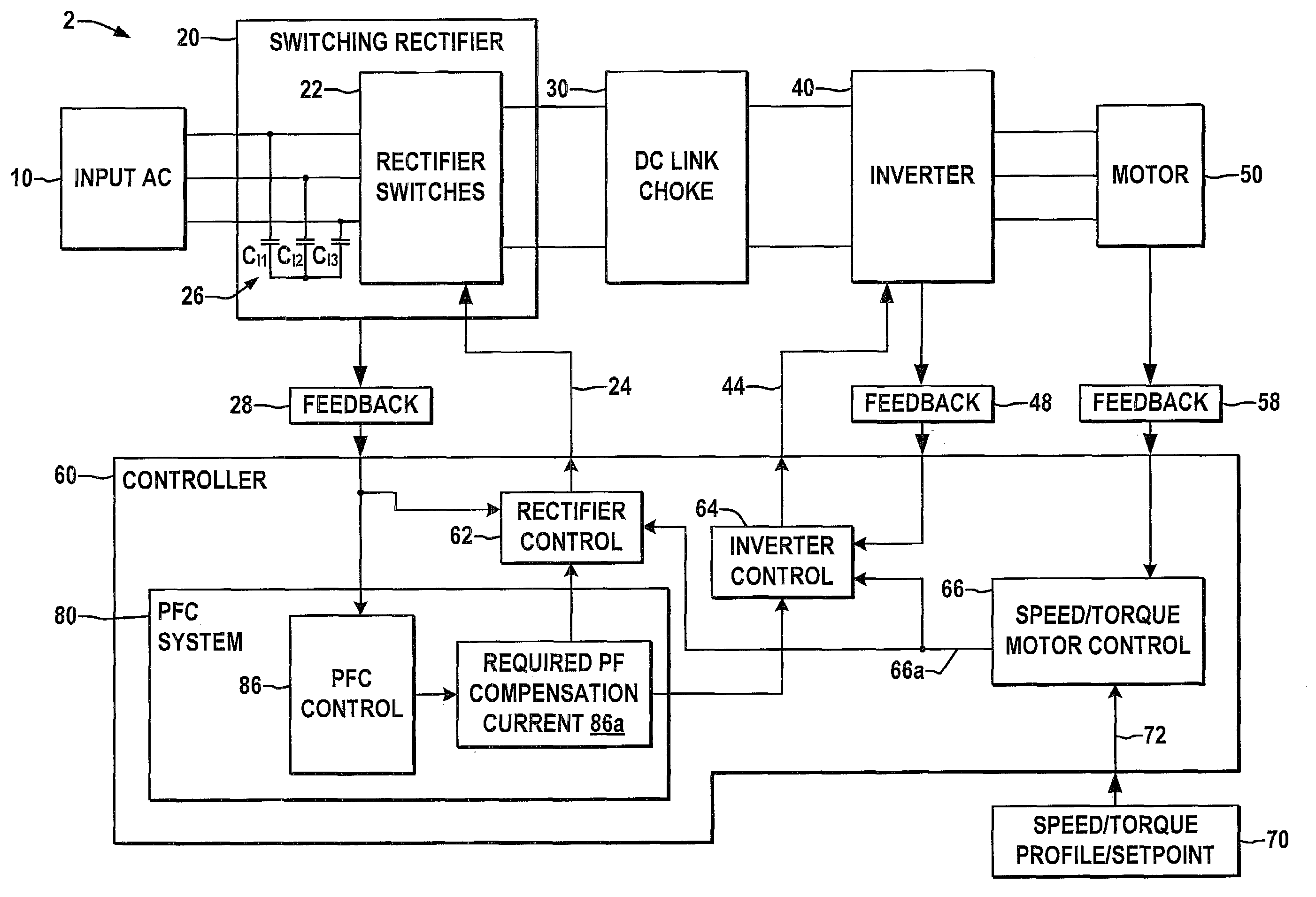
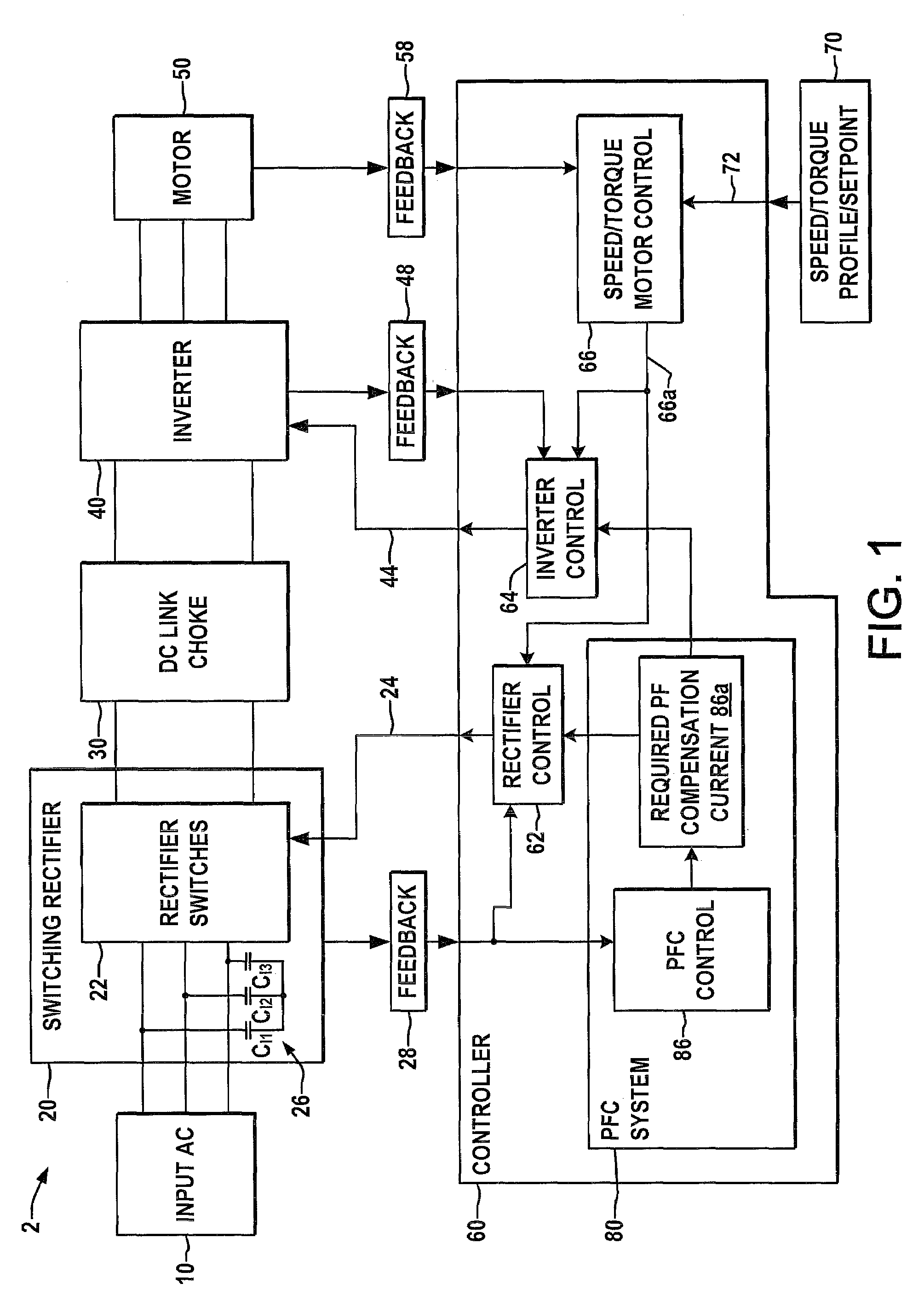
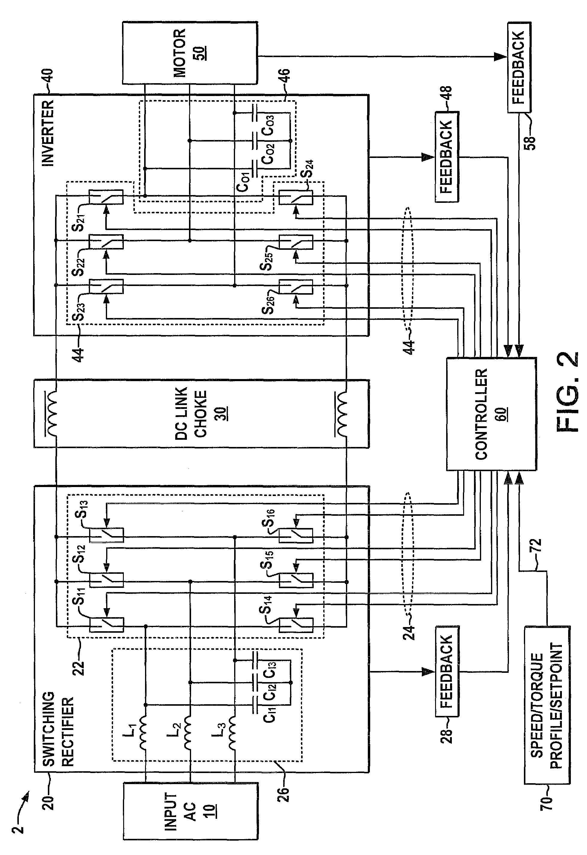
[0015]Referring now to the figures, several embodiments or implementations of the present invention are hereinafter described in conjunction with the drawings, wherein like reference numerals are used to refer to like elements throughout, FIGS. 1-3 illustrate a medium voltage current source motor drive system 2 in accordance with the present disclosure, which receives AC input power from a power supply 10 and provides variable frequency AC power to a motor load 50. The drive 2 includes a switching rectifier 20 with input filter capacitors 26 and a set of rectifier switches 22 operable according to a first set of switch control signals 24 from a controller 60 to provide DC link current to an intermediate DC bus or link having a DC link choke or inductor 30. The DC link current is provided via the link choke 30 to a current source type switching inverter 40 that selectively switches the DC current according to a second set of switch control signals 44 from the controller 60 to power t...


PUM


Abstract

Systems and methods are described for controlling power factor in motor drives having a switching rectifier providing a DC link current to an inverter in which the rectifier gain is increased to provide additional DC link current to correct the drive power factor based on current drawn by capacitors of the AC drive power input, and the inverter gain is decreased by introducing bypass states in the inverter switching control scheme or by reducing the motor flux to accommodate the increased DC link current.

Description

FIELD OF THE INVENTION[0001]The present invention relates generally to electrical power conversion, and more particularly to systems and methods for controlling power factor in motor drive systems.BACKGROUND OF THE INVENTION[0002]Adjustable speed motor drives are power conversion systems that operate to provide power to electric motors in a controlled fashion to control one or more motor performance parameters, such as speed, torque, etc. Medium voltage current-sourced type motor drives typically receive multiphase AC input power in the range of about 2,400 to 6,900 volts, which is converted to DC power referred to as a DC link and provided to an inverter stage. The inverter switches the DC link currents to provide AC output current to a motor load with the output current being controlled by the inverter in closed loop fashion to drive the motor at a desired speed and / or torque. The rectifier is generally an active switching type rectifier that selectively activates switches to prov...

Claims


Application Information

Patent Timeline
Patent Type & Authority Patents(United States)
IPC IPC(8): H02P1/24
CPCH02M1/4216H02M1/4233H02M5/4585H02P23/0081Y02B70/126H02P23/26Y02B70/10Y02P80/10
Inventor ZARGARI, NAVID REZAWISEMAN, JASON CORNELIUSXIAO, YUAN
Owner ROCKWELL AUTOMATION TECH
Why Eureka
Try Eureka