Transmission apparatus with variable impedance matching

a technology of impedance matching and transmission apparatus, which is applied in the field of transmission apparatuses with variable input/output impedance, can solve the problems of difficult reduction of the number of coefficients in the recursive filter unit, less flexible disadvantageously less flexible recursive filter unit than the non-recursive filter unit, so as to reduce the complexity of the circuit

Active Publication Date: 2009-02-24
MAXLINEAR INC
View PDF6 Cites 4 Cited by
  • Summary
  • Abstract
  • Description
  • Claims
  • Application Information

AI Technical Summary

Benefits of technology

[0013]One aspect of the present subject matter is thus to provide a transmission apparatus for transmission of electrical signals between a line driver, which is connected to a transmission line, and a switching center, in which the circuit complexity is reduced.
[0018]Furthermore, the circuit arrangement according to the invention makes it possible for the single digital feedback loop to operate at a signal rate which is lower than the sampling rate of an analog / digital converter.
[0019]According to the invention, feedback is provided in the digital feedback device by means of a feedback filter device which contains recursive and non-recursive filter units, such that the recursive filter units have a lower filter order than the non-recursive filter units. This advantageously considerably reduces the circuit complexity in the digital feedback device for the transmission apparatus.

Problems solved by technology

The conventional circuit arrangement illustrated in FIG. 3 for setting a complex line impedance has significant disadvantages, however.
A further disadvantage is that the digital feedback loop DS1 comprises a recursive filter unit, which is less flexible than a non-recursive filter unit.
A further disadvantage is that it is difficult to reduce the number of coefficients in a recursive filter unit which is arranged as shown in FIG. 3.
A recursive filter unit is disadvantageously less flexible than a non-recursive filter unit.
One major disadvantage of the conventional circuit arrangement illustrated in FIG. 3 is that two digital feedback loops must be provided in the digital circuit part, in addition to the analog feedback loop in the analog circuit part.
This considerably increases the circuit complexity, and disadvantageously leads to an increase in cost.

Method used


Image

  • Transmission apparatus with variable impedance matching
  • Transmission apparatus with variable impedance matching
  • Transmission apparatus with variable impedance matching

Examples


Embodiment Construction

[0042]The same reference symbols in the figures denote identical or functionally identical components or steps.

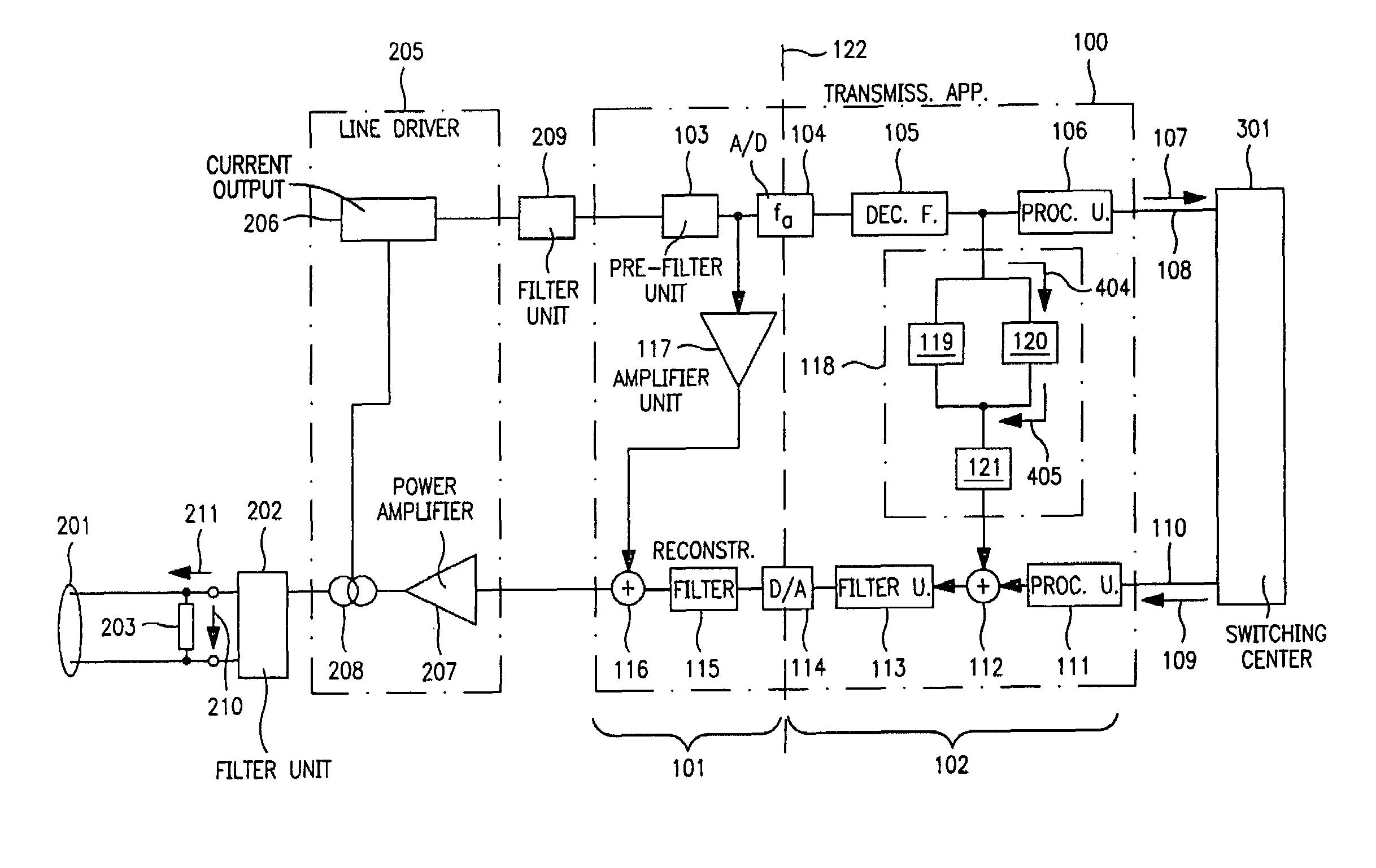
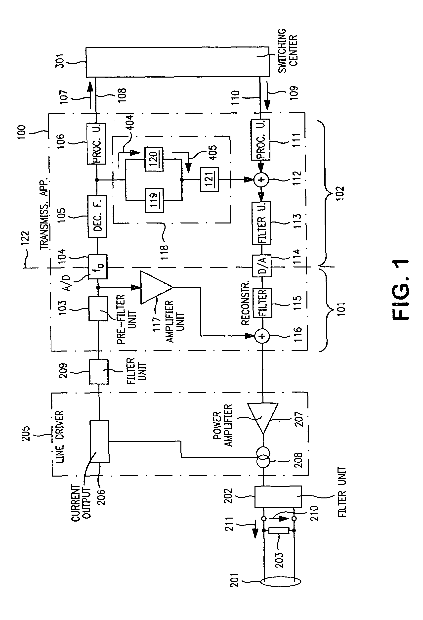
[0043]FIG. 1 shows a transmission apparatus 100, which is designed to transmit electrical signals between a line driver 205, which is connected to a transmission line 201, and a switching center 301. Circuit components which will be described briefly in the following text before describing the transmission apparatus 100 itself are connected between the transmission line 201 and the transmission apparatus 100.

[0044]The transmission line 201 has a line impedance which is represented by a component with the reference symbol 203. The line impedance is the quotient of the line voltage or the line voltage level 210 dropped along the line divided by the current 211 flowing in the line. The line voltage level 210 is the potential difference between a first connection (A conductor) of a first external filter unit 202 and a second connection (B conductor) of the first external filter...


PUM


Abstract

The invention provides a transmission apparatus (100) for transmission of electrical signals between a line driver (205), which is connected to a transmission line (201), and a switching center (301), having an analog feedback device (101) for coarse setting of a line voltage level (210) on the transmission line (201), and a digital feedback device (102), which is coupled to the analog feedback device (101) and has a feedback filter device (118), designed such that a filter input signal (404) can be converted to a filter output signal (405) at a rate which is lower than the sampling rate (fa) of an analog / digital converter (104).

Description

TECHNICAL FIELD[0001]The present invention relates in general to transmission apparatuses with a variable input / output impedance, and relates in particular to a transmission apparatus which provides impedance matching for speech coding / decoding units.BACKGROUND ART[0002]The invention relates specifically to a transmission apparatus for transmission of electrical signals between a line driver, which is connected to a transmission line, and a switching center, having:[0003]a) an analog feedback device for coarse setting of a line voltage level on the transmission line as a function of a line current which is detected in the line driver; and[0004]b) a digital feedback device, which has a feedback filter device for fine setting of an amplitude and phase relationship between the line voltage level and the line current.[0005]FIG. 3 shows a coding / decoding unit (Codec) based on the prior art. The coding / decoding unit is connected via a filter F2 to a line driver (SLIC=Subscriber Line Inter...

Claims


Application Information

Patent Timeline
Patent Type & Authority Patents(United States)
IPC IPC(8): H04M7/04G06F17/10G10L19/00H03H17/02H04B14/04H04L25/12
CPCH04B14/04H04L25/0278H04L25/028
Inventor CANELLA, ALBERTOJENKNER, CHRISTIANSCHWINGSHACKL, DAVID
Owner MAXLINEAR INC
Why Eureka
Try Eureka