Internal combustion engine

a combustion engine and combustion chamber technology, applied in the direction of machines/engines, lasers, mechanical equipment, etc., can solve the problems of less suitable for rapid pulse sequences, complex circuitry is required for control, and the device cannot be housed entirely in a component, and achieve the effect of high amplification

Inactive Publication Date: 2009-03-03
AVL LIST GMBH
View PDF7 Cites 17 Cited by
  • Summary
  • Abstract
  • Description
  • Claims
  • Application Information

AI Technical Summary

Benefits of technology

[0029]For amplification and coherence of the light, the laser crystal is embedded in an optical resonator whose quality is increased in a pulsed manner with the Q-switch upon reaching the desired power density. A short, high laser pulse is thus obtained at the output mirror. A passive Q-switch is used, which on the one hand allows high amplification and on the other hand short energy pulses without any complex control unit.

Problems solved by technology

Actively switchable Q-switches come with the disadvantage however that a considerably complex circuitry is required for the control and that they are less suitable for rapid sequences of pulses.
In combination with the active Q-switch and the pumped light source formed by the flash lamp, the most serious disadvantage is that the device cannot be housed entirely in a component to be screwed into a spark plug shaft.
This known ignition device comes with the disadvantage of a very high constructional complexity and requires a lot of overall space in order to be used instead of a spark plug in an internal combustion engine.
Although the need for compact laser ignition devices has existed for a long time, there have not been any concrete constructional proposals for compact laser ignition devices for internal combustion engines.
Components such as cooling devices which usually require a lot of overall space are missing, which is why these systems are not yet suitable for practical use in internal combustion engines.
In the case of solid state lasers pumped with pump diodes, the problem occurs that the pump diodes can only be operated within a very narrow temperature band.
Excessive temperatures would drastically reduce the service life of the pump diodes.
Cooling alone by Peltier elements is not sufficient for the use as an ignition device in internal combustion engines.
Furthermore, the cooling is subject to further difficulties by the demand that the laser ignition device should be constructed in the highest compact manner and should be housed in the spar plug dome of a cylinder head of an internal combustion engine.

Method used


Image

  • Internal combustion engine
  • Internal combustion engine
  • Internal combustion engine

Examples


Embodiment Construction

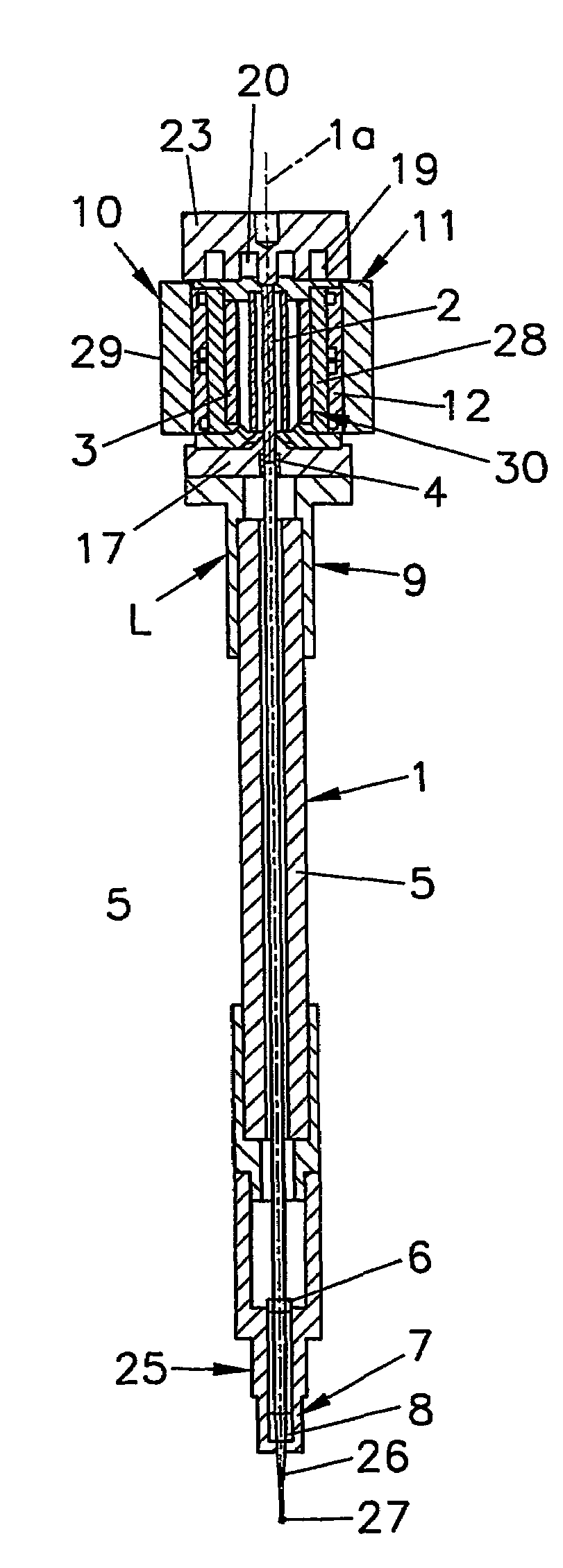
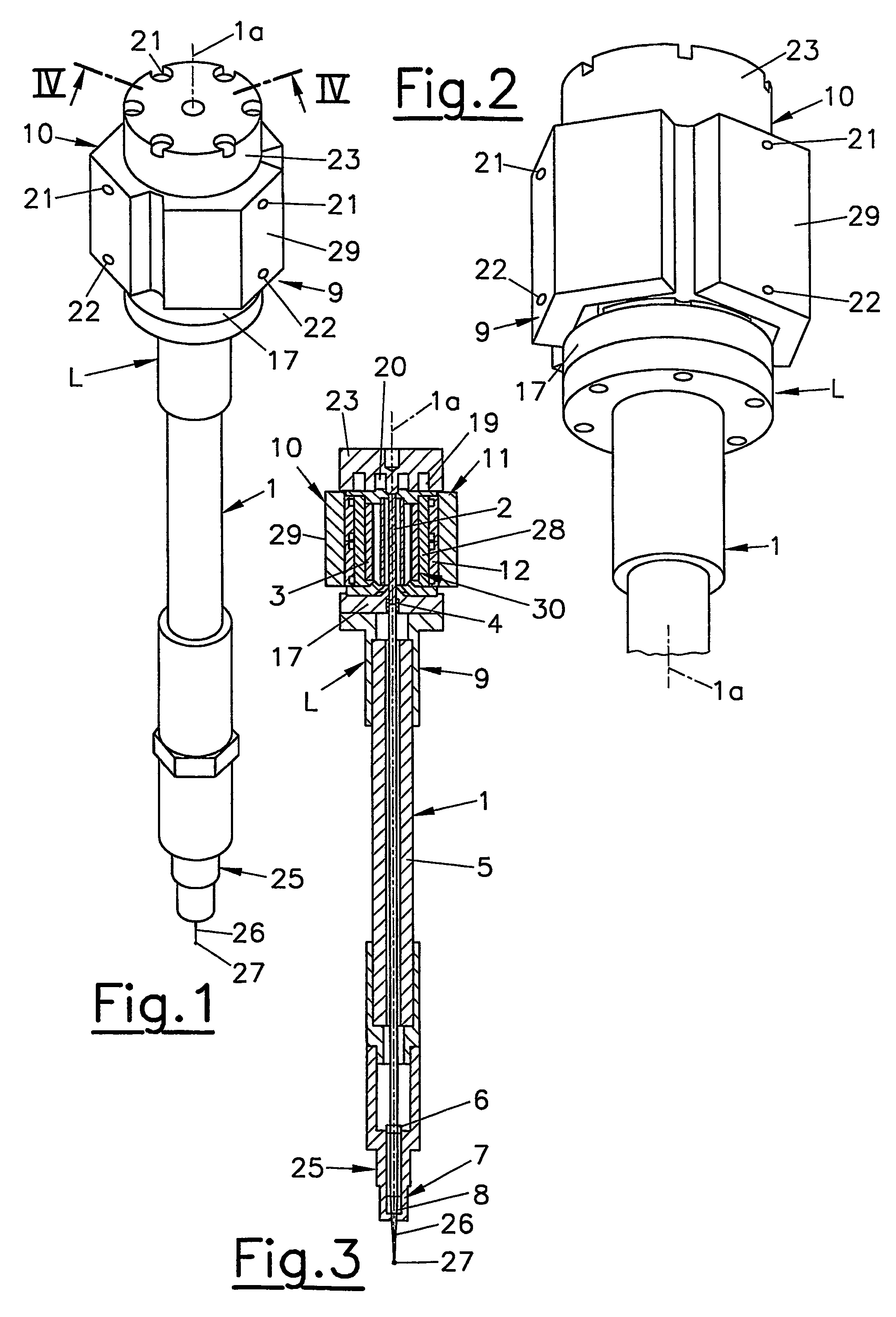
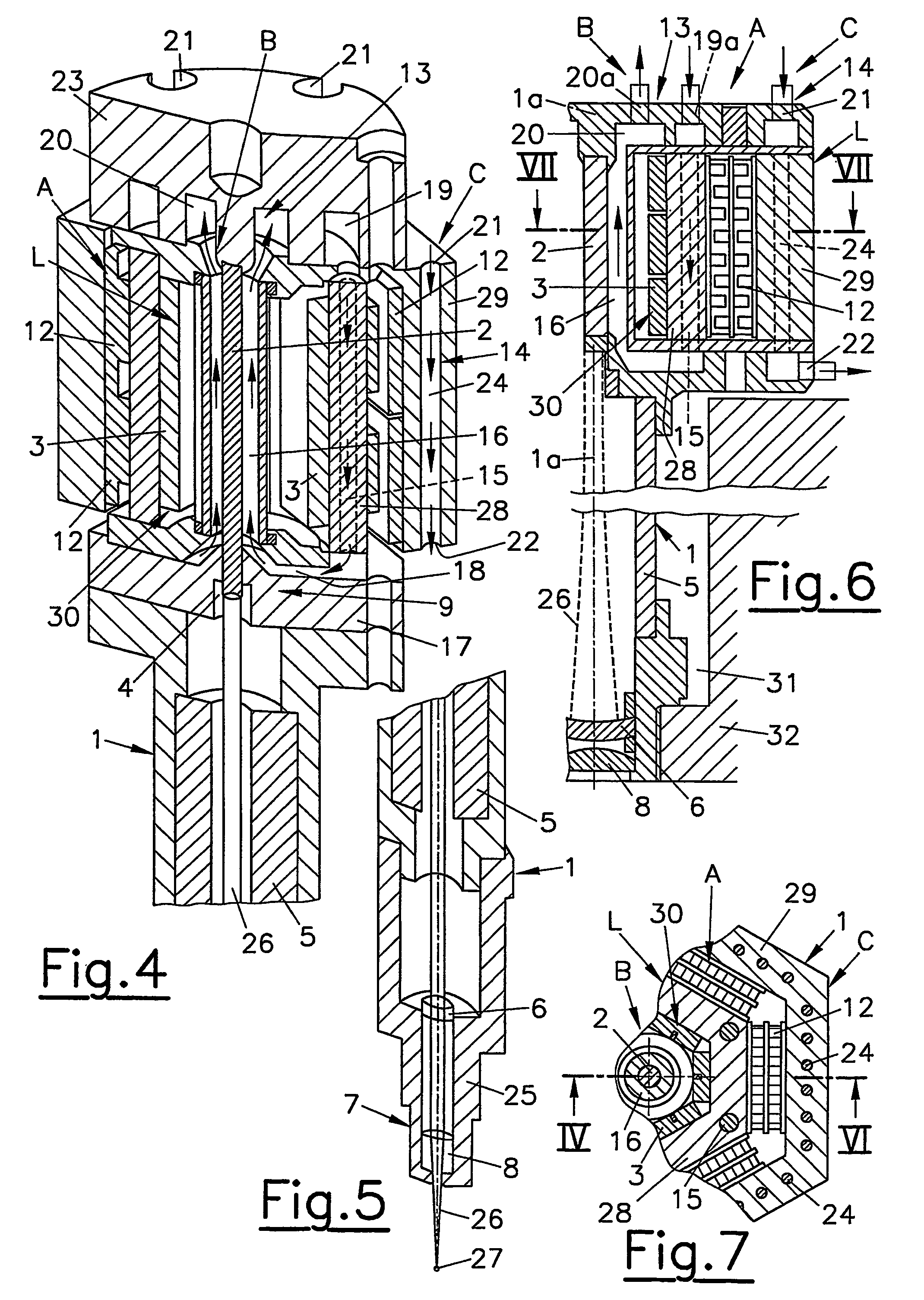
[0043]High efficiency can be achieved when the pumped light source 30 is formed by pump diodes 3.

[0044]Meta-stable energy levels are excited in the laser crystal 2 via irradiation of the pump diodes 3 (808 nm) and the energy is thus stored. As a result of a low spontaneous emission, the laser crystal 2 begins to emit light at laser wavelength (1064 nm).

[0045]For amplification and coherence of the light, the laser crystal 2 is embedded in an optical resonator 9 whose quality is increased in a pulsed manner with the passive Q-switch 4 upon reaching the desired power density. A short, strong laser pulse 26 is thus obtained at the output mirror 6.

[0046]Individual pump diodes 3 are connected in series and are arranged in an annular fashion on the side about the laser crystal 2.

[0047]Due to strongly limited life at higher operating temperatures, the pump diodes 3 need to be operated at a relatively low temperature of approx. 30° C. Moreover, the wavelength of the pump diodes 3 changes wit...


PUM


Abstract

The invention relates to an internal combustion engine with a laser ignition device (1), Q-switched, pumped solid-state laser with a pulsed pumped light source (30), a solid laser crystal (2), enclosed in a resonator, a Q-switch (4), for increasing the power density, at least one output mirror (6) and a focussing device (7), by means of which the laser beam (26) may be focussed in a combustion chamber.

Description

BACKGROUND OF THE INVENTION[0001]1. Field of the Invention[0002]The invention relates to an internal combustion engine with a laser ignition device, comprising a Q-switched, pumped solid-state laser with a pulsed pumped light source, a solid laser crystal embedded in a resonator, a Q-switch for increasing the power density, at least one output mirror and a focusing device, by means of which the laser beam may be focused in a combustion chamber.[0003]The invention further relates to a Q-switched, pumped solid state laser, especially for a laser ignition device of an internal combustion engine, comprising a pulsed pumped light source formed by pump diodes, a solid laser crystal embedded in a resonator, a Q-switch for increasing the power density, at least one output mirror and a focusing device, with a cooling device being provided comprising at least one Peltier cooling element for cooling the resonator.[0004]2. The Prior Art[0005]Q-switched, pumped solid state lasers are especially ...

Claims


Application Information

Patent Timeline
Patent Type & Authority Patents(United States)
IPC IPC(8): H01S3/11F02P23/04H01S3/042H01S3/06H01S3/0941H01S3/102H01S3/113
CPCF02P23/04H01S3/042H01S3/025H01S3/061H01S3/0941H01S3/1024H01S3/113
Inventor WINKLHOFER, ERNSTFRANZ, GEORGKROUPA, GERHARDMANNHEIM, VOLKERBINDER, ALFRED
Owner AVL LIST GMBH
Why Eureka
Try Eureka