Planar transformer power supply

a technology of power supply and planar transformer, which is applied in the direction of electric variable regulation, process and machine control, instruments, etc., can solve the problems of leakage of hf current, and achieve the effect of reducing the negative effect of other operating parameters and minimizing the stray capacitan

Active Publication Date: 2009-03-10
BOVIE MEDICAL CORP
View PDF2 Cites 210 Cited by
  • Summary
  • Abstract
  • Description
  • Claims
  • Application Information

AI Technical Summary

Benefits of technology

[0011]The present invention relates to a split transformer to minimize the stray capacitance and reduce the negative effects of the other operating parameters commonly associated by transformers. In particular, the present invention relates to a planar push-pull output transformer and circuit.
[0014]There are a number of operating advantages inherent in the step-down / step-up transformer configuration including minimizing the stray capacitance to about 5 pF.
[0015]In addition, the use of planar ferrite cores allows cooling heat-sinks to be attached easily to the flat surface of the planar core.

Problems solved by technology

A common problem in the field of electro-surgery is the leakage of HF current.

Method used


Image

  • Planar transformer power supply
  • Planar transformer power supply
  • Planar transformer power supply

Examples


Embodiment Construction

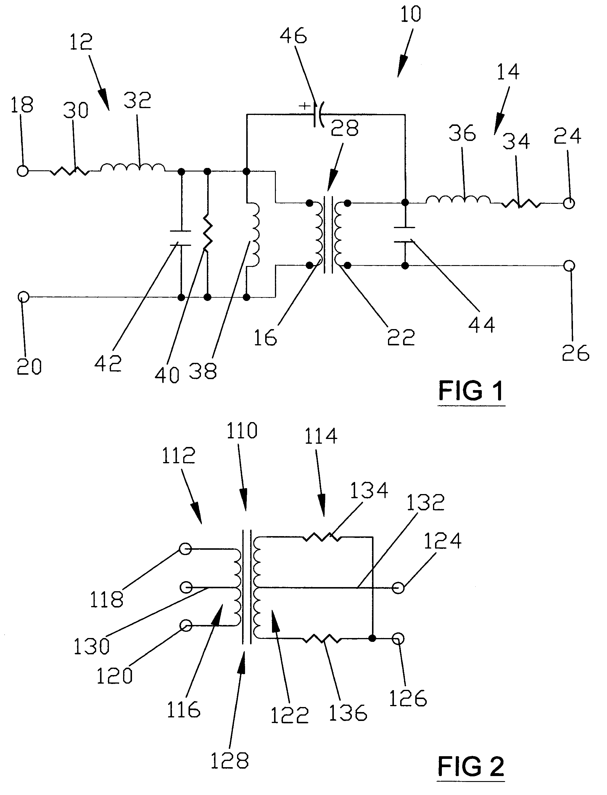
[0023]FIG. 1 depicts an equivalent schematic of a transformer generally indicated as 10 comprising an input section generally indicated as 12 and an output section generally indicated as 14.

[0024]The input section 12 comprises a primary winding 16 coupled across primary input and output terminals 18 and 20; while, the output section 14 comprises a secondary winding 22 coupled across secondary input and output terminals 24 and 26. A transformer core section generally indicated as 28 is disposed in operative relationship relative to the primary and secondary windings 16 and 22.

[0025]Primary stray resistance and primary stray inductance are represented as 30 and 32, respectively; while, secondary stray resistance and secondary stray inductance are represented as 34 and 36 respectively.

[0026]Primary excitation inductance, magnetic resistive core loss and primary winding capacitance are shown as 38, 40 and 42 respectively; while, secondary winding capacitance is shown as 44. Stray capaci...


PUM


Abstract

A planar transformer power supply for an electrosurgical device to minimize stray capacitance comprising a step down / step-up isolation transformer and circuitry to limit the effects of a short circuit in the output of the planar transformer power supply on the input to the planar transformer power supply to enhance power capacity at a low load impedance as low as from about 5 ohms to about 10 ohms and to operate at resonance at the output of the planar transformer power supply.

Description

BACKGROUND OF THE INVENTION[0001]1. Field of the Invention[0002]A planar transformer for an electrosurgical device to minimize stray capacitance.[0003]2. Description of the Prior Art[0004]A common problem in the field of electro-surgery is the leakage of HF current. This leakage depends in large part on stray capacitance. A significant portion of this stray capacitance is attributable to the output transformer of the electro-surgical device or RF unit. Thus, stray capacitance can be reduced or minimized through the proper design of the transformer.[0005]U.S. Pat. No. 4,255,735 discloses a device for transforming an alternating current-voltage which including a core, a primary winding subassembly and a second winding subassembly. One or both of the primary and second winding subassemblies consists of at least one pair of equal turn and approximately equal resistance windings wrapped co-directionally around the core, each having an equal number of tapped sections. A special tandem swi...

Claims


Application Information

Patent Timeline
Patent Type & Authority Patents(United States)
IPC IPC(8): H02M3/335
CPCA61B18/1206H01F27/38H02M5/12A61B2018/1286H01F27/341H01F27/42H01F29/02H01F2019/085H01F2027/2819
Inventor GOLISZEK, GREGORYSHILEV, NICKOLAY DIMITROV
Owner BOVIE MEDICAL CORP
Why Eureka
Try Eureka