Solid oxide fuel cell systems having temperature swing reforming

a technology of solid oxide fuel cell and temperature swing, which is applied in the direction of combustible gas production, sustainable manufacturing/processing, lighting and heating apparatus, etc., can solve the problems of limiting the utility of steam reform furnace in point-of-use fuel applications, occupying a large space, and substantially greater than the volume of tubes

Inactive Publication Date: 2009-03-17
EXXON RES & ENG CO
View PDF13 Cites 92 Cited by
  • Summary
  • Abstract
  • Description
  • Claims
  • Application Information

AI Technical Summary

Benefits of technology

[0009]The present invention provides an improvement in the process of producing electricity from fuel cells where the fuel cell is fueled with a hydrocarbon containing synthesis gas. A cyclic reforming process, referred to as temperature swing reforming, provides an efficient means for producing a hydrogen containing synthesis gas for fuel cell applications. Temperature swing reforming is integrated with a solid oxide fuel cell to achieve thermal and material efficiencies relative to conventional fuel processor / fuel cell systems. In one embodiment the temperature swing reforming process is physically integrated with the SOFC. The integrated design results in high system efficiency. Specific embodiments are detailed hereinafter.
[0016]The feed stream space velocity (i.e. greater than about 500 hr−1) is based upon the entire bed area. The temperature swing reforming process efficiently produces a hydrogen containing synthesis gas that is used to fuel a high temperature fuel cell, typically a solid oxide fuel cell.

Problems solved by technology

Unfortunately, steam reforming furnaces occupy a very large volume of space, substantially greater than the tube volume.
This feature, and the relatively low efficiency, combine to severely limit its utility in point-of-use fuel applications such as fuel cells and would likely be unfeasible for on-board vehicle applications or distributed power applications.
However, these patents describe a process that operates at very low productivity, with space velocities of around 100 hr−1 (as C1-equivalent).
One consequence of Sederquist's low space velocity is that resulting high heat losses impede their ability to achieve high efficiency.

Method used


Image

  • Solid oxide fuel cell systems having temperature swing reforming
  • Solid oxide fuel cell systems having temperature swing reforming
  • Solid oxide fuel cell systems having temperature swing reforming

Examples


example 1

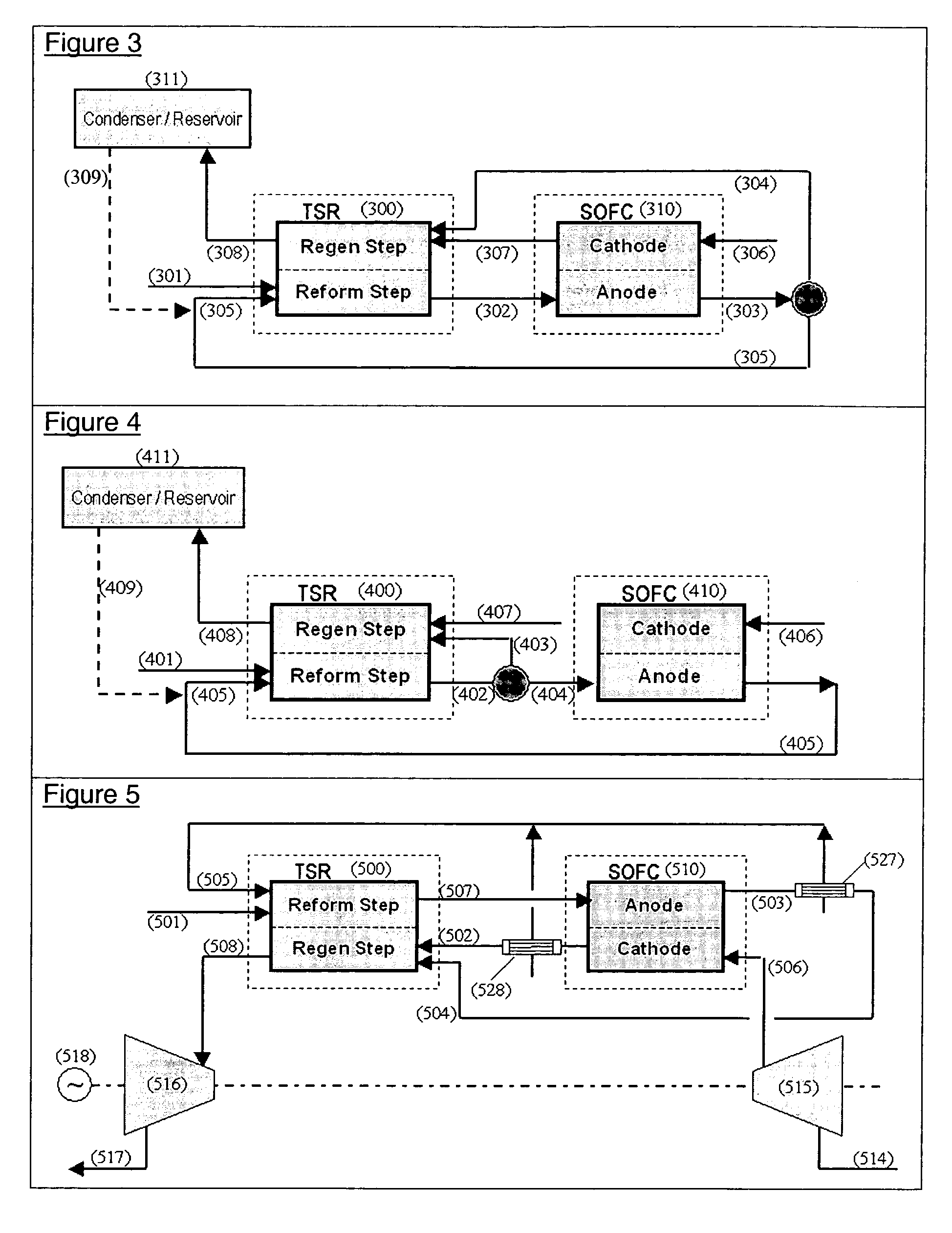
[0064]The following example is included to better illustrate aspects of the present invention. An amount of methane was used as a feed to the integrated TSR / SOFC system illustrated in FIG. 3. The results shown are for methane feed at about 8000C1 GHSV and a 3-second TSR cycle time. The steam / carbon ratio into the reforming side is about 1.5. Hydrogen utilization in the fuel cell stack is about 0.8, CO utilization is about 0.39. In typical operations, the hydrogen utilization and relative reaction rate / utilization of H2 and CO will vary with fuel cell type membrane chemistry, temperature and other cell parameters. The split of stream (303) is about 53% into (305) and about 47% into (104). Key operating and process parameters are identified in the following Table 1.

[0065]

TABLE 1301303304307308StreamRef-302SOFC-FC-H2-305Rgn-CathodeRegengmolsFdRef-outoutrxRfm-RcyFuelEffluentEffluentTemp C.500542527504P0.50.30.20.20.20.20.1AtmGaCH44.070.120.1200.050.070H2002.7313.0506.196.868.46H2012.92....


PUM

PropertyMeasurementUnit
inlet temperatureaaaaaaaaaa
temperatureaaaaaaaaaa

Abstract

The present invention provides an improvement in the process of producing energy from fuel cells. A cyclic reforming process, referred to as temperature swing reforming, provides an efficient means for producing a hydrogen containing synthesis gas for use in solid oxide fuel cell applications. In one embodiment, at least some synthesis gas which is first produced in the temperature swing reforming process is combusted with air to provide the heat for the regeneration step of the temperature swing reforming process. The syngas produced in TSR is particularly well suited for use in solid oxide fuel cell applications.

Description

[0001]This application claims the benefit of U.S. Provisional Application No. 60 / 472,864 filed May 23, 2003.FIELD OF THE INVENTION[0002]The present invention relates to process improvements in the production of hydrogen from hydrocarbon fuel and its use in fuel cells. More particularly, the invention relates to a process scheme wherein synthesis gas produced in a cyclic reforming process is integrated with and used in a solid oxide fuel cell (“SOFC”). The cyclic reforming process is herein referred to as “Temperature Swing Reforming” or “TSR” for short. In temperature swing reforming, the reforming step of the synthesis gas production is followed by a regeneration step. The hydrogen stream produced by TSR is particularly well suited for use in a SOFC being at temperatures conducive to efficient use by that type of fuel cell. In a preferred embodiment, TSR is integrated physically with the SOFC to increase the overall efficiency of the system. The present invention provides an effici...

Claims


Application Information

Patent Timeline
Patent Type & Authority Patents(United States)
IPC IPC(8): C01B3/32C01B3/36C10J3/46C10J3/54F28D21/00B01J19/24C01B3/38C01B3/46H01M8/04H01M8/12
CPCB01J19/2485C01B3/38C01B3/46H01M8/04097H01M8/0618H01M8/0637C01B2203/0233C01B2203/066C01B2203/0805C01B2203/0811C01B2203/0822C01B2203/0827C01B2203/1011C01B2203/1023C01B2203/141C01B2203/148C01B2203/1614C01B2203/1671H01M2008/1293Y02E60/50Y02E60/525Y02P20/10C01B3/26C01B3/14
Inventor HERSHKOWITZ, FRANKBERLOWITZ, PAUL J.
Owner EXXON RES & ENG CO
Why Eureka
Try Eureka