Electric power generating apparatus for movement type equipment and self-generation system having the same

a technology of electric power generation and movement type equipment, which is applied in the direction of electrical equipment, piezoelectric/electrostrictive/magnetostrictive devices, piezoelectric/electrostriction/magnetostriction machines, etc., can solve the problems of device not operating, battery replacement is required, energy conversion efficiency is low, etc., and achieves high energy conversion efficiency

Inactive Publication Date: 2009-03-17
KOREA INST OF SCI & TECH
View PDF33 Cites 20 Cited by
  • Summary
  • Abstract
  • Description
  • Claims
  • Application Information

AI Technical Summary

Benefits of technology

[0016]Therefore, an object of the present invention is to provide an electric power generating apparatus for a movement type equipment having a high energy conversion efficiency.
[0017]Also, an object of the present invention is to provide an electric power generating apparatus for a movement type equipment having a high energy conversion efficiency even when too much load is applied in a direction parallel to a piezoelectric beam or in constant speed rotation.

Problems solved by technology

However, since electric power for operating a sensor and transferring a signal depends on only batteries, periodical change of battery is required.
However, processing of complicated shape is required in the tire, and energy conversion efficiency is low.
Also, since centrifugal force is much stronger than gravity in a constant speed movement, force is applied only in a radius direction and the device does not operate.

Method used


Image

  • Electric power generating apparatus for movement type equipment and self-generation system having the same
  • Electric power generating apparatus for movement type equipment and self-generation system having the same
  • Electric power generating apparatus for movement type equipment and self-generation system having the same

Examples


first embodiment

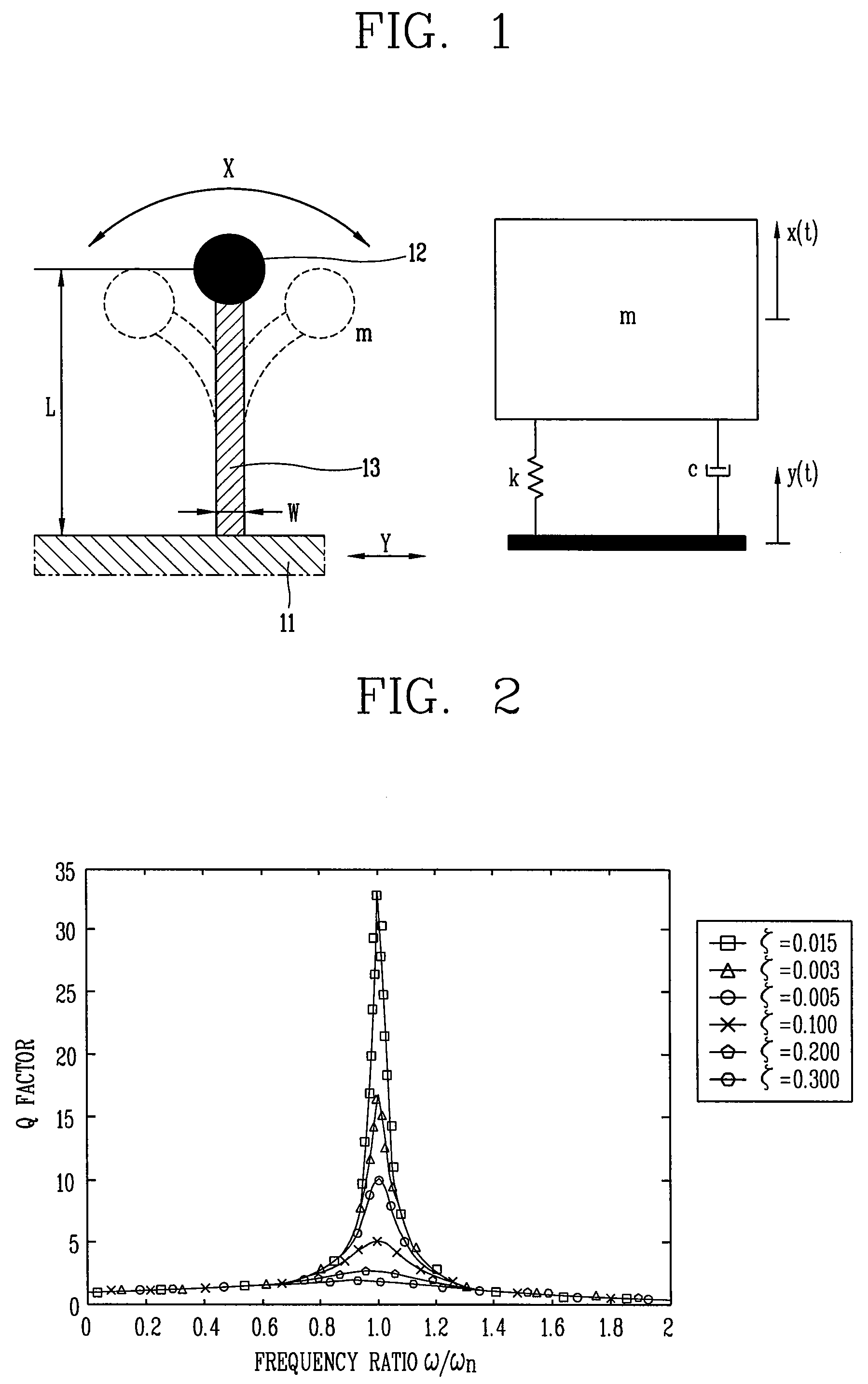
[0040]FIG. 1 is a view illustrating a basic structure of an electric power generating apparatus for a movement type equipment and m-c-k modeling thereof according to the present invention. Herein, L represents a length of a piezoelectric beam, w represents a width, m represents mass, k represents spring constant, c represents damping coefficient, x represents amplitude of a mass part, and y represents amplitude of a base. FIG. 2 is a graph illustrating displacement transmissibility (Q) for the m-c-k modeling of FIG. 1 depending on variation of a frequency ratio (ω / ωn) and a damping ratio (ζ).

[0041]Referring to FIGS. 1 and 2, an electric power generating apparatus according to a first embodiment of the present invention includes a piezoelectric beam 13 and a rectifier unit (not shown). The piezoelectric beam 13 has one end of the piezoelectric beam 13 fixed to a movement type equipment 11 and other end with a mass 12. The rectifier unit rectifies and stores electric energy generated ...

second embodiment

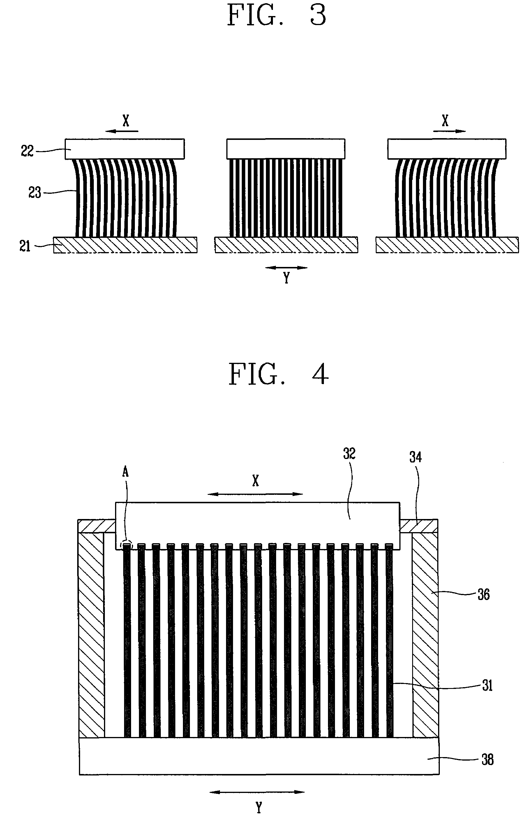
[0048]Referring to FIG. 3, the electric power generating apparatus for the movement type equipment according to the present invention includes a plurality of piezoelectric beams 23 having ends fixed to a movement type equipment 21, a mass part 22 for connecting other ends of the piezoelectric beams 23 with one another, and a rectifier unit (not shown) for rectifying and storing electric energy generated due to deformation of the piezoelectric beams 23.

[0049]Since a single beam has a limit in generating energy, sufficient energy may not be obtained. Therefore, in order to solve such a problem, the electric power generating apparatus for the movement type equipment according to the second embodiment of the present invention includes the plurality of piezoelectric beams 23 disposed in a row on the movement type equipment 21. In this case, since the voltage generated from parallel disposition has displacement of the same phase, the magnitude of generated electric energy increases in pro...

third embodiment

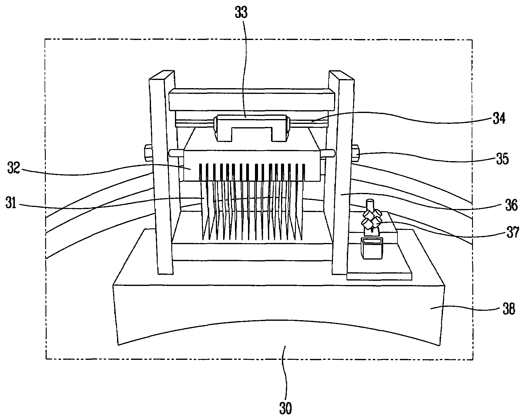
[0051]Referring to FIGS. 4 to 6, the electric power generating apparatus for the movement type equipment according to the present invention includes a base 38, a plurality of piezoelectric beams 31, a mass part 32, a guide unit, a support member 36, a stopper 35, and a rectifier unit 37. The base 38 is mounted on a movement type equipment 30 and the piezoelectric beams 31 are mounted in a row on the base 38. A plurality of mounting grooves 32a are formed in the mass part 32 to connect other ends of the piezoelectric beams 31 to one another, and other ends of the piezoelectric beams 31 are inserted into the mounting grooves 32a. The guide unit guides the mass part 32 so as to slide in an X direction perpendicular to the piezoelectric beams 31. The support member 36 supports the guide unit and the stopper 35 limits the movement range of the mass part 32. The rectifier unit 37 rectifies and stores electric energy generated due to deformation of the piezoelectric beams 31.

[0052]When a m...


PUM


Abstract

Provided are an electric power generating apparatus for a movement type equipment and a self-generation system having the same. The electric power generating apparatus for a movement type equipment includes: a piezoelectric beam having an end fixed to a movement type equipment and other end with a mass; and a rectifier unit for rectifying and storing electric energy generated due to deformation of the piezoelectric beam. The self-generation system includes: a movement type equipment; and an electric power generating apparatus for a movement type equipment including a piezoelectric beam having an end fixed to a movement type equipment and other end with a mass, and a rectifier unit for rectifying and storing electric energy generated due to deformation of the piezoelectric beam. According to the electric power generating apparatus for the movement type equipment and the self-generation system having the same, since external movement is converted into vibration perpendicular to an electric beam using elasticity of the electric beam and load applied to an end of the beam, continuous vibration is induced to the piezoelectric beam. Also, high energy conversion efficiency can be obtained by using resonance.

Description

RELATED APPLICATION[0001]The present disclosure relates to subject matter contained in priority Korean Application No. 10-2006-0107440, filed on Nov. 1, 2006, which is herein expressly incorporated by reference in its entirety.BACKGROUND OF THE INVENTION[0002]1. Field of the Invention[0003]The present invention relates to an electric power generating apparatus for a movement type equipment and a self-generation system having the same, and more particularly, to an electric power generating apparatus for a movement type equipment capable of generating electric power using vibration, periodical movement, and rotation of a movement type equipment without supply of a battery or external energy and a self-generation system having the same.[0004]2. Description of the Background Art[0005]Mobility of all electronic equipments will be generalized in future life. Therefore, various types of mobile power source will be developed and commonly used. In a power source of a wireless sensor, an inte...

Claims


Application Information

Patent Timeline
Patent Type & Authority Patents(United States)
IPC IPC(8): H01L41/113
CPCH02N2/18H01L41/1136H10N30/306H02N2/00
Inventor CHANG, YOUNG-SOOLEE, HEON-JULEE, YOON-PYO
Owner KOREA INST OF SCI & TECH
Why Eureka
Try Eureka