
Automatic testing equipment instrument card and probe cabling system and apparatus

a technology of automatic testing and instrument card, applied in the direction of electrical testing, measurement devices, instruments, etc., can solve the problems of limited accuracy and breadth of automatic testing capabilities, interference and distortion of signal transmission through pogo pin connections, and the configuration of pogo pins cannot accommodate the full performance capability of devices, etc., to achieve more reliable and efficient testing, high performance

Active Publication Date: 2009-03-17
TERADYNE
View PDF36 Cites 17 Cited by
  • Summary
  • Abstract
  • Description
  • Claims
  • Application Information

AI Technical Summary

Benefits of technology

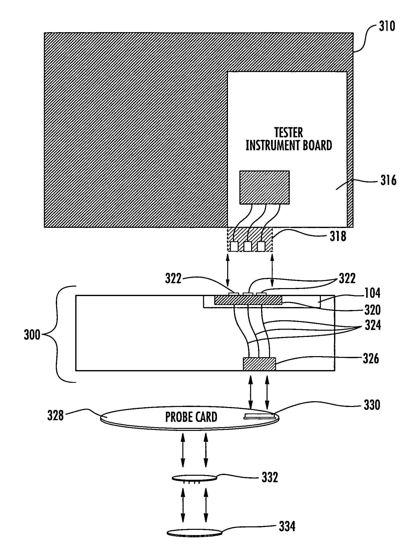
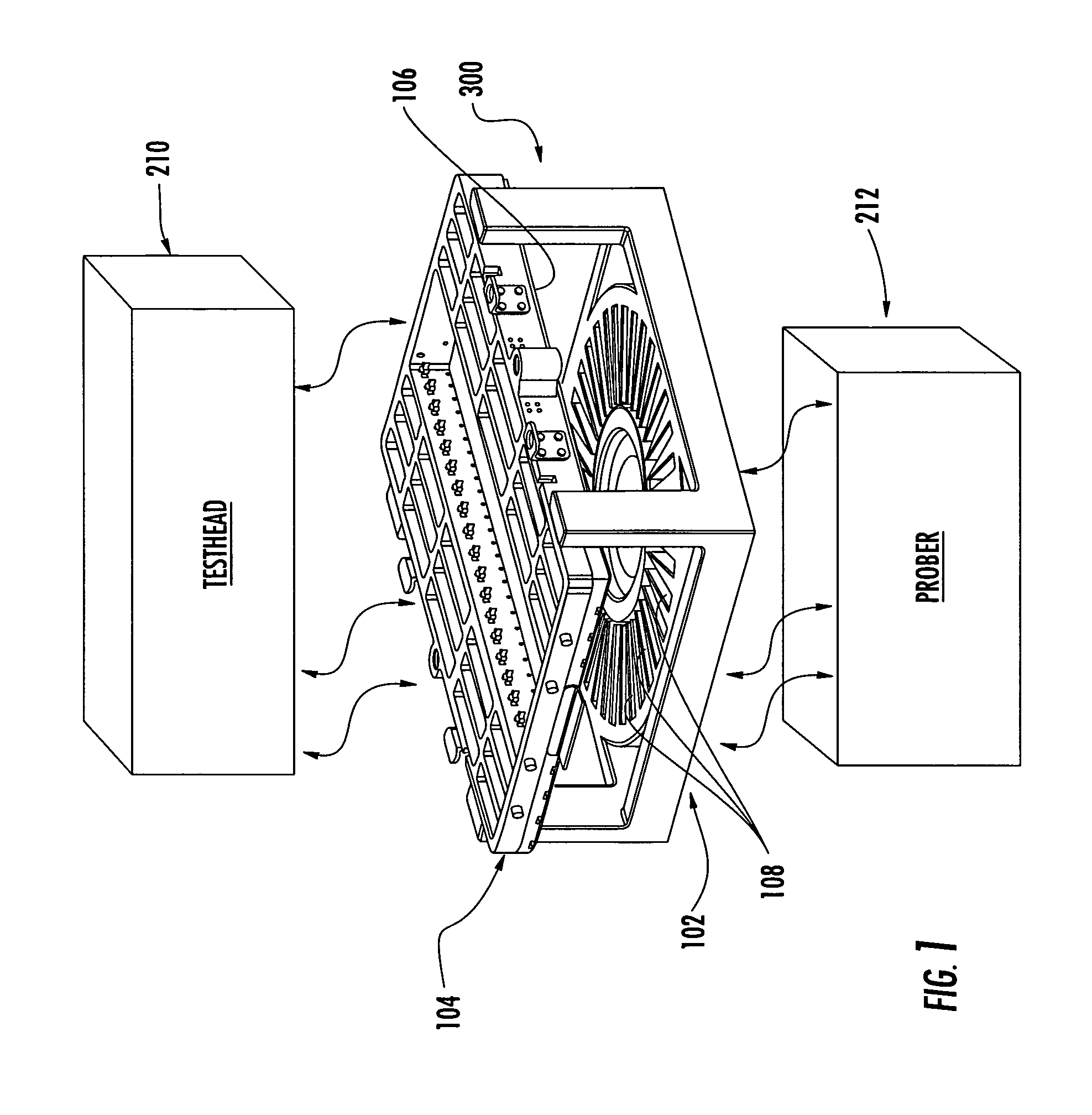
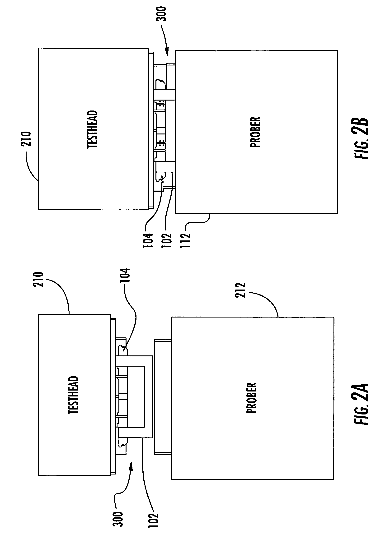
[0004]Various embodiments of the invention provide for a device for interfacing a test head to a wafer, or device under test. In an illustrative embodiment, high performance wires or cables are used to provide the connection from the probe card interface boards to the probe card. The use of wires or cables, in place of the traditional printed circuit board (“PCB”) or printed wiring board (“PWB”) arrangements allow for more reliable and efficient testing. A stiffening member may serve as a mounting frame for the device interface boards. The stiffening member may have an internal lattice structure creating a series of open passages that may be used to pass wires or locate circuit components. The stiffening member may have multiple sidewalks and individual, configuration-specific probe card interface strips may be connected to a probe card through low-friction connections such as zero-insertion force clamps or pneumatic connectors. As used herein, the term “sidewalk” is used to refer to each passage row. The probe interface attaches to the test head using standard probe interface board docking mechanics. The assembly is then connected to a prober to carry out the testing procedures.
[0006]Various embodiments of the present invention can provide a reliable and configurable testing assembly for automatic test equipment environments. In an illustrative embodiment, the probe card interface has a device interface circuit that communicates with a probe card through a zero-insertion force clamp. The clamp engages an electrical connector that is coupled to the probe card. An embodiment of the present invention also includes a method of testing equipment automatically. In this embodiment, the probe card interface is secured to a test head and wired to communicate with the test head. The probe card is inserted into the probe assembly and connected through the zero-insertion force clamp. A controller on the test head transmits a signal from the test head to the probe assembly and onto the probe card. The probe card may be coupled with wafer probe technology and the device being tested. Data from the test signal is returned through the probe assembly and back to the controller on the test head.

Problems solved by technology

The use of the pogo pin arrangements creates limitations in the accuracy and breadth of the testing capabilities of ATE.
The pogo pin configuration is not able to accommodate the full performance capability of the device being tested and can yield unreliable results.
Signal transmission though the pogo pin connections is subject to interference and distortion, which can effect test results in the automated environment.
The requirement of producing new boards for every configuration drastically increases the cost of testing and producing electrical devices.
The replacement of the PIB and the probe card in the probe card interface is time consuming and expensive.

Method used


Image

  • Automatic testing equipment instrument card and probe cabling system and apparatus
  • Automatic testing equipment instrument card and probe cabling system and apparatus
  • Automatic testing equipment instrument card and probe cabling system and apparatus

Examples


Embodiment Construction

[0016]Embodiments of the present invention can provide a reliable and cost effective test head / prober interface for automatic test equipment (“ATE”). In some implementations, the present invention can provide increased reliability of the testing procedures. The elimination of pogo pins or spring pins reduces reliability and performance problems experienced in the field. Additionally, the modularization of the device interface circuitry can ease the interchangeability of instruments as well as reducing cost in the manufacture and design of ATE system configurations.

[0017]Turning now to FIG. 1, a perspective view of an example embodiment of a probe interface 300 is depicted. An assembly frame 102 contains four leg-like structures for the support of a stiffening member 104. The stiffening member 104 securely mounts to the assembly frame 102 through a screw attachment. A probe interface board 106 is mounted to the underside of the stiffening member 104. The probe interface board 106 con...


PUM


Abstract

A device for interfacing a test head and a prober is disclosed using wires or cables to provide the connection from a probe card interface boards to the probe card. The use of wires or cables, in place of the traditional pogo pin arrangement allows for more reliable and efficient testing, as well as additional high performance tests to be run. Optionally, a probe interface contains a stiffening member with multiple sidewalks and individual, configuration-specific probe card interface strips are connected to a probe card through zero insertion force clamps. The probe card interface attaches to the test head using standard probe interface board (“PIB”) docking mechanics. The assembly is then connected to a probe to carry out the testing procedures.

Description

FIELD OF THE INVENTION[0001]The present invention relates to automated testing equipment, more specifically a probe interface and method for automatic test equipment.BACKGROUND OF THE INVENTION[0002]Automatic test equipment (“ATE”) has been known in the art for several years. Automating the testing procedures for circuit boards and electronic devices expedites the testing process and allows for greater production of tested electronic devices. When testing an instrument, a probe card or wafer interface is attached to a test head. A probe then docks with the test head through the probe interface using methods well known in the art. The probe interface contains a probe interface board (“PIB”) and a probe card. The probe card makes an electrical connection to the PIB through a series of pogo pin, or spring pin, arrangements, typically in the form of a ring. The pogo pin arrangements are limited to 4650 pins per probe card. The PIB is a printed circuit board (“PCB”) or a printed wiring b...

Claims


Application Information

Patent Timeline
Patent Type & Authority Patents(United States)
IPC IPC(8): G01R31/02
CPCG01R1/07378G01R31/2889
Inventor PARRISH, FRANK B.BEHZIZ, ARASH
Owner TERADYNE
Learn More