Systems and methods for real-time compensation for non-linearity in optical sources for analog signal transmission

a technology of analog signal transmission and real-time compensation, applied in the field of analog optical source and transmission, can solve the problems of module laser replacement, performance degradation, and become an expensive proposition, and achieve the effect of gaining the feedback loop

Active Publication Date: 2009-03-17
CIENA
View PDF43 Cites 1 Cited by
  • Summary
  • Abstract
  • Description
  • Claims
  • Application Information

AI Technical Summary

Benefits of technology

[0005]In various exemplary embodiments, the present invention provides a compact analog directly modulated laser configuration that is suitable for use in the field that uses electrical feedback to compensate for non-linearity in real time, such that no matter how the LI curve changes, the electrical feedback compensates for non-linearity by amplifying a portion of the output analog optical signal and combining it with the input analog electrical signal using the standard control method of negative feedback. When the gain of the feedback loop is relatively high, the overall transfer function of the system is primarily dependent on the feedback loop gain block, which is substantially linear. This is accomplished by incorporating a relatively large bandwidth photo-detector at the back facet of the laser that both monitors the output power of the system and provides a feedback signal to the linearization control circuit, as well as an amplifier. The amplified signal from the relatively large bandwidth photo-detector is used to correct for various undesirable effects, such as non-linearity and relative intensity noise (RIN) of the laser. The signal from the relatively large bandwidth photo-detector also allows the laser to operate effectively close to threshold.

Problems solved by technology

Thus, the directly modulated lasers must be replaced regularly, likely as often as once every few months, as performance degradation occurs.
Due to their relatively high cost, this becomes an expensive proposition.
This problem is exacerbated by the fact that optical network elements are continually being deployed closer to end users.
Thus, these optical network elements are being deployed in uncontrolled “field” environments.
Similarly, the externally modulated lasers that compensate, to some extent, for non-linearity suffer from component complexity and are also relatively expensive.

Method used


Image

  • Systems and methods for real-time compensation for non-linearity in optical sources for analog signal transmission
  • Systems and methods for real-time compensation for non-linearity in optical sources for analog signal transmission
  • Systems and methods for real-time compensation for non-linearity in optical sources for analog signal transmission

Examples


Embodiment Construction

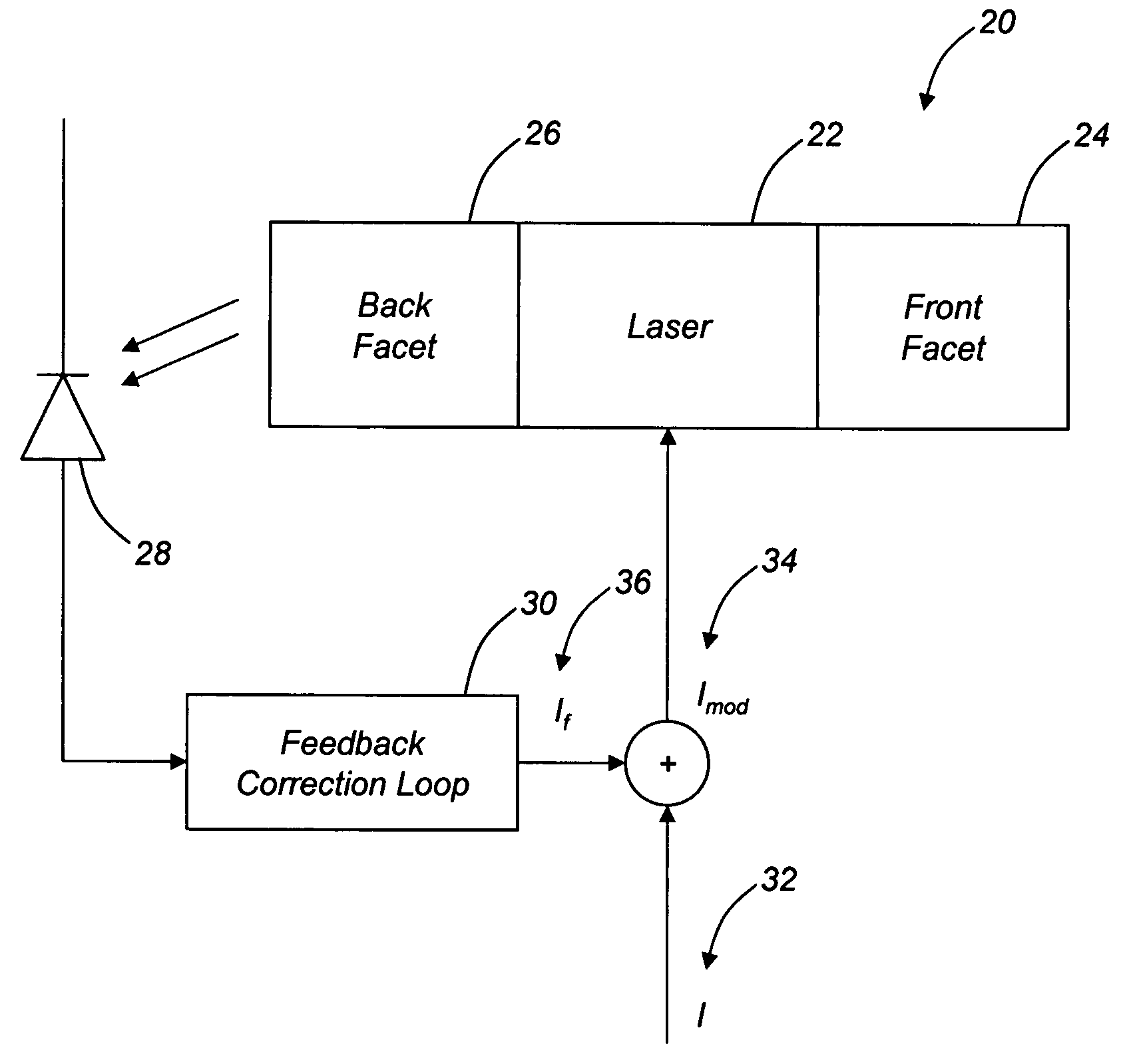
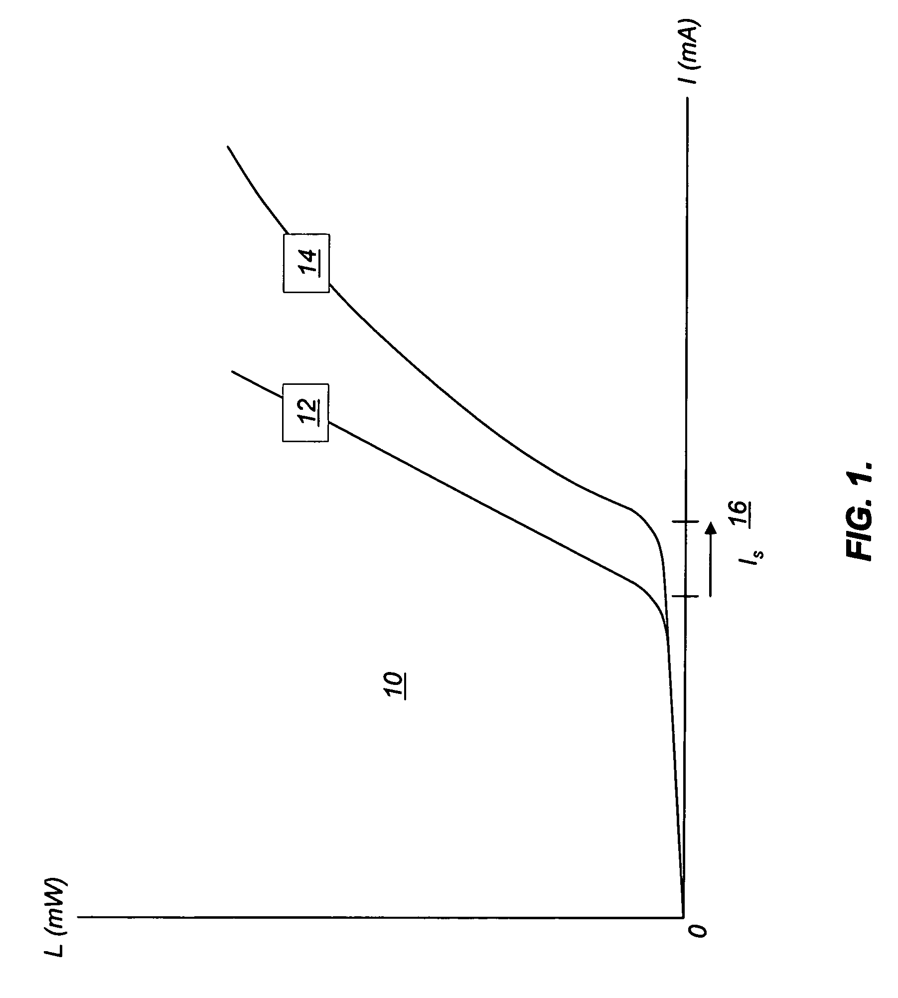
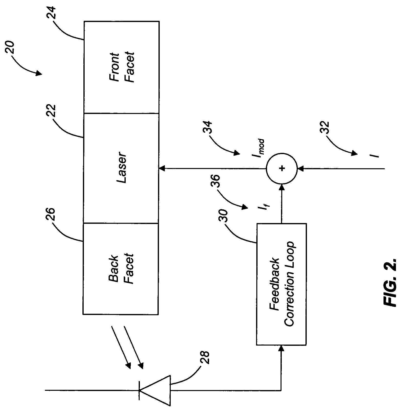
[0014]As described above, analog optical signals can be generated using highly-linear directly modulated lasers, such as semiconductor lasers, laser diodes, and the like. In general, the characteristic curves 10 (FIG. 1) (optical power in mW vs. injection current in mA) (LI curves) of these lasers must be substantially linear and curve or “kink”-free above a threshold current 16 (FIG. 1) (Is) at which lasing begins. Referring to FIG. 1, for example, a substantially linear characteristic curve 12 and a substantially non-linear characteristic curve 14 above Is 16 are illustrated. Alternatively, analog optical signals can be generated using externally modulated lasers to compensate, to some extent, for any non-linearity. The overall requirement, using either modulation scheme, is that the generated analog optical signals closely match the input analog electrical signals, without significant distortion. In other words, slope variation compensation must be incorporated in order to mainta...


PUM


Abstract

The present invention provides a compact analog directly modulated laser configuration that is suitable for use in the field that uses electrical feedback to compensate for non-linearity in real time, such that no matter how the LI curve changes, the electrical feedback compensates for non-linearity by amplifying a portion of the output analog optical signal and combining it with the input analog electrical signal using the standard control method of negative feedback. When the gain of the feedback loop is relatively high, the overall transfer function of the system is primarily dependent on the feedback loop gain block, which is substantially linear. This is accomplished by incorporating a relatively large bandwidth photo-detector at the back facet of the laser that both monitors the output power of the system and provides a feedback signal to the linearization control circuit, as well as an amplifier. The amplified signal from the relatively large bandwidth photo-detector is used to correct for various undesirable effects, such as non-linearity and relative intensity noise (RIN) of the laser. The signal from the relatively large bandwidth photo-detector also allows the laser to operate effectively close to threshold.

Description

FIELD OF THE INVENTION[0001]The present invention relates generally to the analog optical source and transmission fields. More specifically, the present invention relates to systems and methods for real-time compensation for non-linearity in optical sources for analog (radio frequency (RF)) signal transmission and the like. The systems and methods of the present invention find applicability related to the distribution of voice transmission signals, video transmission signals, cable television (CATV) signals, wireless backhauling signals, cellular / personal communications system (PCS) signals, personal optical network (PON) signals, sensing signals, phased-array radar signals, and the like via analog optical links. The solution of the present invention can be applied to a variety of small form-factor (SFF) connector and small form-factor pluggable (SFP) modular optical transceiver packaging standards, including transmitter optical subassemblies (TOSAs), receiver optical subassemblies ...

Claims


Application Information

Patent Timeline
Patent Type & Authority Patents(United States)
IPC IPC(8): H01S3/00
CPCH01S5/06832H01S5/0427
Inventor SHAHINE, MICHAEL H.
Owner CIENA
Why Eureka
Try Eureka