Container, storing bath and a method of producing the container

a technology of storing bath and container, which is applied in the direction of manufacturing converters, furnaces, charge manipulation, etc., can solve the problems of container requiring very long time, troublesome drying step, and pressure inside the container to rise to an unexpected level, so as to improve the “ability to hold” of the storing bath and the strength of the indeterminate form refractory material.

Inactive Publication Date: 2009-03-24
HOEI SHOKAI CO LTD
View PDF15 Cites 3 Cited by
  • Summary
  • Abstract
  • Description
  • Claims
  • Application Information

AI Technical Summary

Benefits of technology

[0007]The present invention is made to overcome such problem, and the object of this invention is to provide a container that is capable of preventing unexpected rise of the pressure inside the container caused by the problem pertaining to the lining.
[0072]According to the present invention, the productivity of manufacturing container can be improved. Although raw materials of a container of this type are inexpensive, it has many manufacturing steps such as molding, drying and the like, therefore, the cost of manufacturing can be reduced according to the present invention.

Problems solved by technology

However, as described in the patent literature 1, in a hermetically closed-type container that supplies the molten metal to an outside using a pressure difference, a fluid component contained in the lining and a component of the lining crystallized as an aqueous solution evaporated by the heat of the molten metal inside container, causing the pressure inside the container to rise to an unexpected level.
In order to prevent such case, it is necessary to dry the lining thoroughly after the step of molding thereof, however, being comprised of a plurality of layers, the drying step is very troublesome.
For this reason, there is a problem that the production of the container requires very long time, thus the productivity thereof is very low.
For example, when the cracking reaches from a space inside the container to the flow path, a gas for applying pressure directly flows through the cracking portion into the flow path, and the supply of the molten metal becomes unstable.
Furthermore, there is also a problem in that the molten metal in a state of containing the gas therein is blown out of the pipe and molten metal with high temperature is splattered in a surrounding area.
However, such cracking in the lining is inevitably caused by mechanical vibration given to the container when being transported, a thermal expansion of the molten metal etc.
However, there is a problem in that such relining being very inefficient since a plurality of layers must be coated and dried.

Method used


Image

  • Container, storing bath and a method of producing the container
  • Container, storing bath and a method of producing the container
  • Container, storing bath and a method of producing the container

Examples


Embodiment Construction

[0035]Hereinafter, embodiments of the present invention will be described with reference to the drawings.

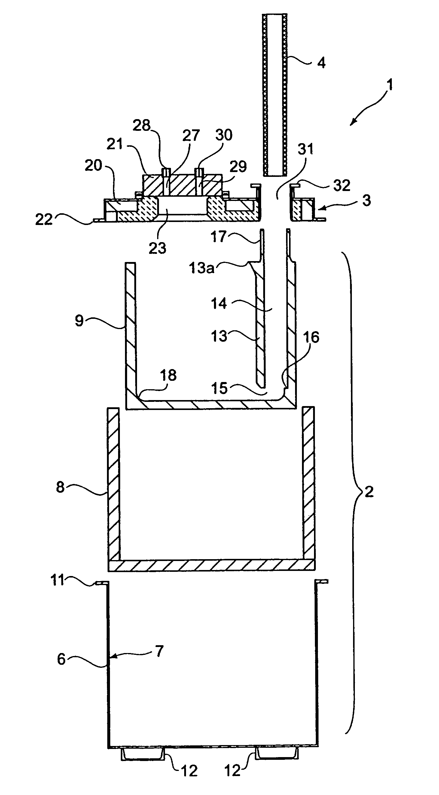
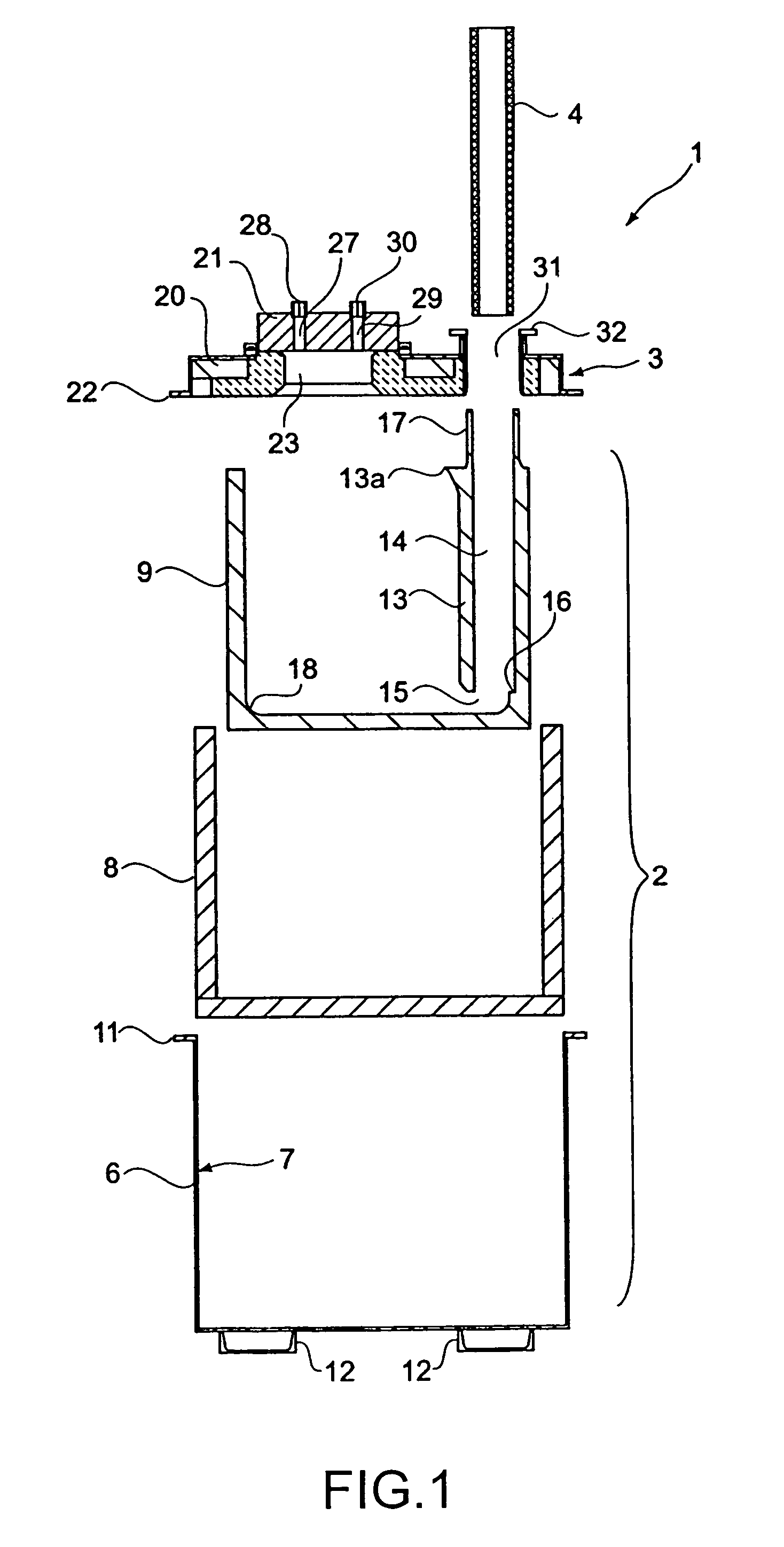
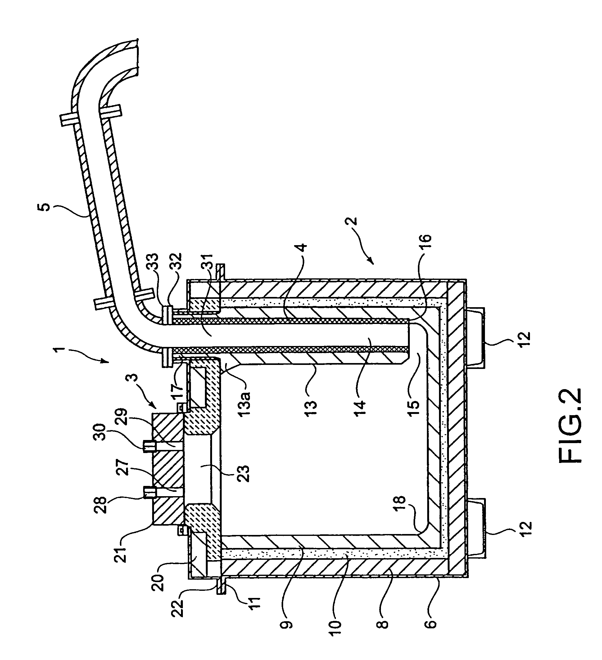
[0036]FIG. 1 is an exploded view of the container in connection with an embodiment of the present invention, FIG. 2 is a sectional view of the container in assembly, FIG. 3 is a front view thereof, FIG. 4 is a plane view without a lid and FIG. 5 is a plane view with a lid.

[0037]A container 1 is comprised of a container body 2, a lid 3 and a first pipe 4 and a second pipe 5.

[0038]The container body 2 has a frame body 6 made of metal bottomed and approximately cylindrically shaped having an opening at a top thereof, a heat-insulating wall 8 laid on an inner wall 7 of the frame body 6 having an elasticity, and a refractory storing bath 9 detachably disposed on the innerwall 7 side of the heat-insulating wall from the opening of the frame body 6.

[0039]A refractory and heat-insulating member 10 in granule form or powder form is inserted in a space between the heat-insulating wall 8 an...


PUM

PropertyMeasurementUnit
temperatureaaaaaaaaaa
depthaaaaaaaaaa
depthaaaaaaaaaa

Abstract

A container (1) and method of manufacturing, capable of preventing unexpected rise of pressure inside the container (1) caused by problems pertaining to the lining. The container has a structure such that the insulating wall (8) is laid on the inner side of the frame body (6), and the refractory storing bath (9) is detachably inserted through the opening (5) of the frame body into the container.

Description

FIELD OF THE INVENTION[0001]This invention is related, for example, to a container suitable for transporting molten aluminum, a bath used for the container and a method of producing the container.BACKGROUND OF THE INVENTION[0002]In a factory where aluminum is molded using many die-casting machines, an aluminum material is often supplied not only from within the factory but also from outside of the factory. In such a case, a container storing aluminum in a melt is carried from a factory on the material supply side to a factory on the molding side to supply to each of the die-casting machines the material kept in the melt. (For example, see the patent literature 1)[0003]A container of this kind is produced, for example, by coating a plurality of layers such as a heat-insulating layer or a refractory layer onto an inner wall of the frame made of metal.[0004][Patent Literature]JP-UM-A-3-31063 (FIG. 1)DISCLOSURE OF THE INVENTIONProblems to be Solved[0005]However, as described in the pate...

Claims


Application Information

Patent Timeline
Patent Type & Authority Patents(United States)
IPC IPC(8): C21C5/44C21B7/04B65D90/00B22D17/06B22D35/00B22D39/06B22D41/02B22D41/12B65D90/02F27D1/00F27D1/10F27D3/14
CPCB22D17/06B22D41/02F27D3/14F27D1/0006B22D41/12B22D41/00F27D1/0003B22D35/00B22D39/06
Inventor MIZUNO, HITOSHIABE, TSUYOSHI
Owner HOEI SHOKAI CO LTD
Why Eureka
Try Eureka