
Method for determining strain hardening property of line pipe

a strain hardening property and pipe technology, applied in the direction of pipes, electrical/magnetic measuring arrangements, mechanical means, etc., can solve the problems of overdesigned system, high probability, and inability to determine local buckling that is allowable in reality, and achieves high pressure for mass transportation, small thickness, and large diameter

Active Publication Date: 2009-04-07
JFE STEEL CORP
View PDF5 Cites 5 Cited by
  • Summary
  • Abstract
  • Description
  • Claims
  • Application Information

AI Technical Summary

Benefits of technology

This approach allows for the design of pipes that meet both economic and safety requirements by accurately determining strain hardening properties, reducing the likelihood of overdesign and cost overruns, and enabling the use of high-strength pipes with smaller thicknesses, thus optimizing pipeline construction costs.

Problems solved by technology

(1) A Problem Occurring Due to the Local Buckling Check Carried Out on the Basis of Experimental Equations
Therefore, when the local buckling is checked with the critical local buckling strain determined on the basis of such design equations, there is a high probability that a local buckling that is allowable in reality may not be determined to be allowable due to the too safe determination in some cases.
This leads to an overdesigned system and cost overruns.

Method used


Image

  • Method for determining strain hardening property of line pipe
  • Method for determining strain hardening property of line pipe
  • Method for determining strain hardening property of line pipe

Examples


first embodiment

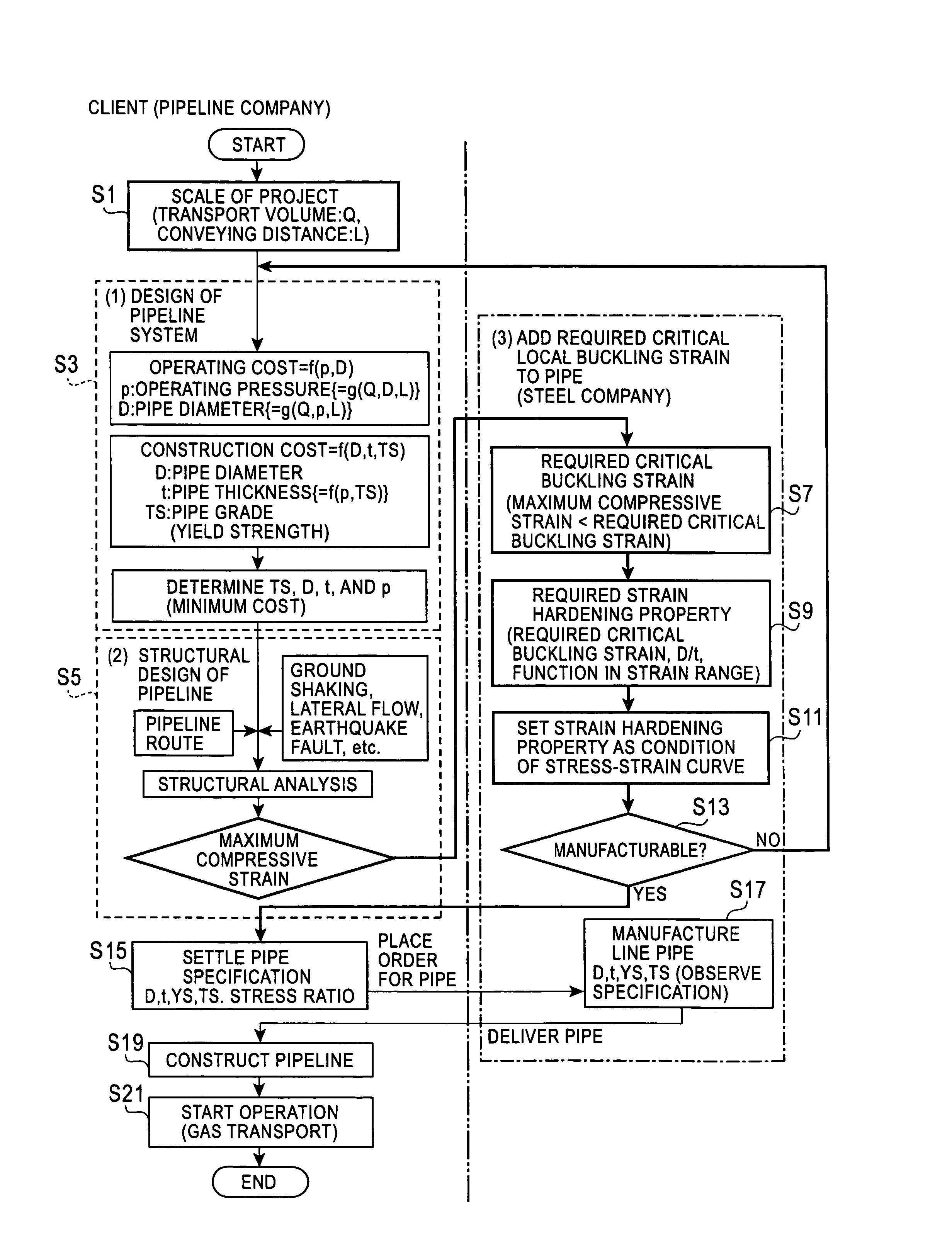
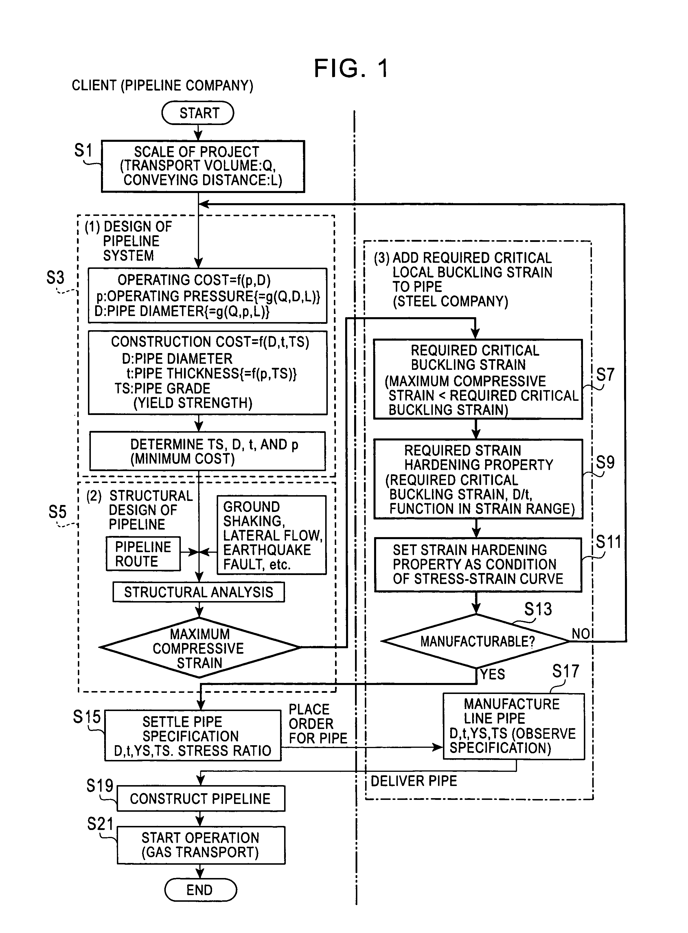
[0166]FIG. 1 presents a flow chart illustrating a method for determining a strain hardening property of a pipe according to a first embodiment of the present invention. As shown in FIG. 1, this embodiment includes a step of defining pipe dimensions where a diameter D, a thickness t, and a transport pressure of a pipe used for a pipeline are temporally set (S3) on the basis of at least transport volume and conveying distance of pressurized fluid transported by the pipeline, the transport volume and the conveying distance being determined according to a project (S1); a step of calculating the maximum axial compressive strain where the structure of the pipeline is designed with consideration of the pipeline route with the pipe having the diameter and the thickness that have been temporally set, and the maximum axial compressive strain generated in the pipe when the transport pressure, ground displacement and / or an external force are exerted on the designed pipeline is determined (S5); ...

second embodiment

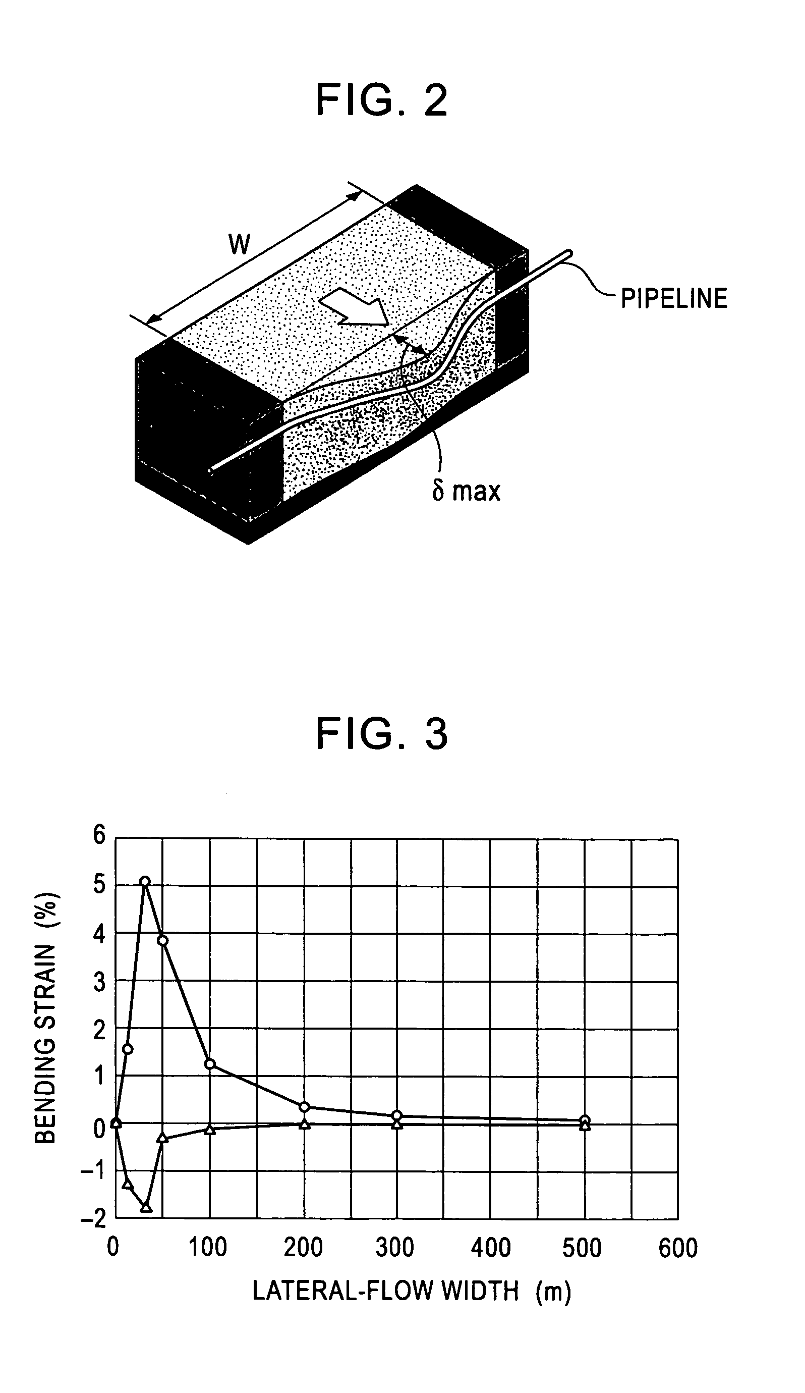
[0187]This embodiment relates to a method for determining a strain hardening property for avoiding local buckling resulting from a lateral fault. Since the flow of processes in this embodiment is basically the same as that in the first embodiment, duplicated parts are described in brief, and different parts are described in detail.

Step of Defining the Pipe Dimensions

[0188]As in the first embodiment, on the premise of the transport volume and the conveying distance of the pressurized fluid transported by the pipeline, the diameter D, the thickness t, and the transport pressure of the pipe are temporally set such that the operating cost and the construction cost are minimized.

[0189]The characteristics of the pipe temporally set in this embodiment are the same as those set in the first embodiment: the outside diameter D=610.0 mm, the pipe thickness t=12.2 mm, the material grade TS: API 5L X80, and the designed internal pressure=10 MPa. According to API 5L X80, a standardized minimum yi...


PUM

PropertyMeasurementUnit
yield pointaaaaaaaaaa
displacementaaaaaaaaaa
axial compressive strainaaaaaaaaaa

Abstract

A method for determining a strain hardening property of a pipe enabling reduction of costs while ensuring pipeline integrity is provided. Moreover, a method for manufacturing a pipe based on the method for determining the strain hardening property of the pipe, a pipe manufactured by means of the method for manufacturing the pipe, and a pipeline are proposed. The method for determining the strain hardening property of the pipe according to the present invention includes a step of defining pipe dimensions where a diameter D, a thickness t, and a required critical local buckling strain εreq of the pipe are set as conditions to be satisfied; a step of acquiring a strain hardening property for acquiring the strain hardening property in the vicinity of a buckling point of the pipe satisfying the conditions set in the step of defining the pipe dimensions; and a step of setting the strain hardening property as a condition to be satisfied by the stress-strain curve of the pipe.

Description

[0001]This application is the United States national phase application of International Application PCT / JP2004 / 018858 filed Dec. 10, 2004.TECHNICAL FIELD[0002]The present invention relates to methods for determining strain hardening properties of pipes that are used for gas and oil pipelines and the like, relates to methods for manufacturing pipes, relates to pipes, and relates to pipelines.BACKGROUND ART[0003]Gas pipelines and oil pipelines have been built as the basis of energy supply. Recently, many gas fields have been developed in places remote from consuming regions with increasing demand, particularly for natural gas, as the backdrop. Accordingly, pipelines have shown a tendency to be longer, and have developed an obvious tendency to have larger diameters and to be highly pressurized for mass transport.[0004]FIG. 13 shows a flow chart of the process of pipeline construction focusing on the design of such pipelines. The conventional process of pipeline design is broadly classi...

Claims


Application Information

Patent Timeline
Patent Type & Authority Patents(United States)
IPC IPC(8): G01B5/30F16L9/02
CPCC21D9/08C22C38/00G06F17/50Y10T29/49G06F2217/34G06F30/00G06F2113/14F16L9/00
Inventor SUZUKI, NOBUHISAMASAMURA, KATSUMI
Owner JFE STEEL CORP
Learn More