In-situ continuous coke deposit removal by catalytic steam gasification

a technology of continuous coke and gasification, which is applied in the direction of combustible gas production, cleaning using liquids, bulk chemical production, etc., can solve the problems of increasing the heat load and temperature of the air available for cooling, increasing the cost of operation, and increasing the heat load

Inactive Publication Date: 2009-04-07
RTX CORP
View PDF21 Cites 3 Cited by
  • Summary
  • Abstract
  • Description
  • Claims
  • Application Information

AI Technical Summary

Problems solved by technology

Thermal management is a significant challenge in advanced aircraft, rocket, and missile engines.
Increasing aircraft speed and engine thrust-to-weight ratio results in large, simultaneous increases in heat load and temperature of the air available for cooling.
Although cryogenic fuels, such as liquid methane and liquid hydrogen, can provide sufficient cooling, they present issues in the areas of cost, logistics, operations, and safety.
However, the decomposition of hydrocarbon fuel at elevated temperatures leads to coke deposition within the fuel passages.
The coke deposits which form in the heat exchangers, reactors, and on the fuel system component walls degrade heat transfer and fuel flow characteristics and, if left unchecked, can lead to system failure.

Method used


Image

  • In-situ continuous coke deposit removal by catalytic steam gasification
  • In-situ continuous coke deposit removal by catalytic steam gasification
  • In-situ continuous coke deposit removal by catalytic steam gasification

Examples


Embodiment Construction

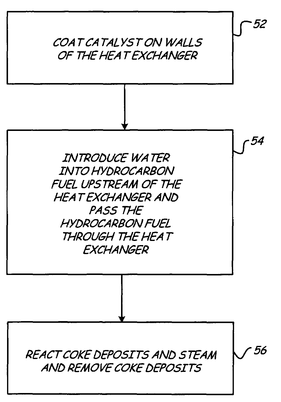
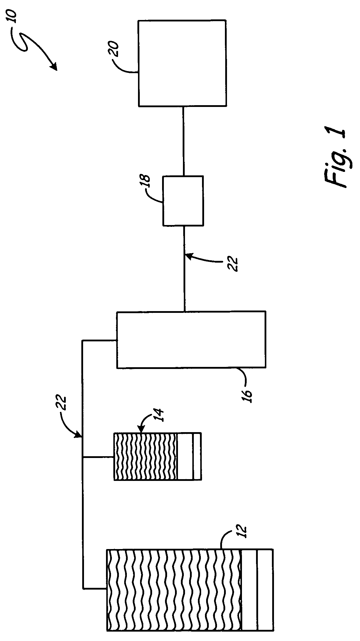
[0011]FIG. 1 shows a block diagram of high temperature system 10 using high heat sink fuel cooling technology with catalytic carbon-steam gasification coke removal. High temperature system 10 can be any system requiring high operating temperatures, such as a gas turbine or a hypersonic scramjet. High temperature system 10 generally includes fuel reservoir 12, water or steam supply system 14, heat exchanger 16, injector 18, combuster 20, and piping 22. Hydrocarbon fuel is stored in fuel reservoir 12 and is pumped to heat exchanger 16 through piping 22 when needed. After the hydrocarbon fuel has been reacted, it is passed through injector 18 to combuster 20. Combuster 20 provides power, or propulsion, to high temperature system 10.

[0012]Hydrocarbon fuel flows through high temperature system 10 and can be any type of hydrocarbon, including any hydrocarbon fuel that is susceptible to coking at elevated temperatures such as gas turbine fuels and other kerosene-type hydrocarbon fuels. For...


PUM

PropertyMeasurementUnit
temperatureaaaaaaaaaa
temperaturesaaaaaaaaaa

Abstract

A coke removal system removes coke deposits from the walls of a high temperature passage in which hydrocarbon fuel is present. The system includes a carbon-steam gasification catalyst and a water source. The carbon-steam gasification catalyst is applied to the walls of the high temperature passage. The water reacts with the coke deposits on the walls of the high temperature passage to remove the coke deposits from the walls of the high temperature passage by carbon-steam gasification in the presence of the carbon-steam gasification catalyst.

Description

BACKGROUND OF THE INVENTION[0001]The present invention relates generally to the field of removing coke from high temperature hydrocarbon systems.[0002]Thermal management is a significant challenge in advanced aircraft, rocket, and missile engines. Increasing aircraft speed and engine thrust-to-weight ratio results in large, simultaneous increases in heat load and temperature of the air available for cooling. Engine and vehicle cooling must therefore be accomplished by using the fuel as a cooling means. One method of cooling advanced engines is the application of high heat sink fuel cooling technology. Although cryogenic fuels, such as liquid methane and liquid hydrogen, can provide sufficient cooling, they present issues in the areas of cost, logistics, operations, and safety. By contrast, conventional liquid hydrocarbon fuels undergoing endothermic chemical cracking, catalytically and / or thermally, offer the required cooling capacity without the problems associated with cryogenic f...

Claims


Application Information

Patent Timeline
Patent Type & Authority Patents(United States)
IPC IPC(8): B08B9/00
CPCB08B9/027C10G9/00C10G11/00C10J3/00F01D25/002C10J2300/0943C10J2300/0973C10J2300/0983C10G2300/708F05D2260/607Y02T50/675Y02T50/60Y02P20/52
Inventor HUANG, HE
Owner RTX CORP
Why Eureka
Try Eureka