Imaging apparatus having a read out circuit unit with dual readout operation and method of improving a frame rate

a readout circuit unit and readout operation technology, applied in the field of imaging apparatus, can solve the problems of difficult to follow an object moved outside the predetermined area, difficulty in adapting the pixel addition to a part, and lower resolution of the pixel addition, so as to achieve the effect of improving the frame ra

Inactive Publication Date: 2009-04-07
CANON KK
View PDF33 Cites 43 Cited by
  • Summary
  • Abstract
  • Description
  • Claims
  • Application Information

AI Technical Summary

Benefits of technology

[0009]The present invention has been made in view of the above problems and has for its purpose to provide an image apparatus capable of improving a frame rate to prevent resolution in the predetermined area from decreasing and forming image signals outside the predetermined area.
[0012]According to the present invention, image signals are read out with a scanning time shortened outside the predetermined area which is not required for surgical operation and diagnosis and only a target portion (or the predetermined area) being a portion required for surgical operation and diagnosis is scanned, so that a required resolution can be obtained in the predetermined area without scarifying the frame rate.
[0013]According to the present invention, a single radiation imaging apparatus can adapt to wider imaging means from fluoroscopy of small parts to plain radiographing of chest, improving the workflow of operation and lightening a burden to a patient.

Problems solved by technology

However, the pixel addition is lower in resolution than the method in which signals are sequential read out.
For this reason, it may be difficult for the pixel addition to adapt to a part such as a heart that moves quickly and has minute vessels.
Accordingly, when the trimming is used for monitoring when a catheter is inserted or surgical operation is conducted in fluoroscopy, images outside the predetermined area cannot be formed, so that it may be difficult to follow an object moved outside the predetermined area.

Method used


Image

  • Imaging apparatus having a read out circuit unit with dual readout operation and method of improving a frame rate
  • Imaging apparatus having a read out circuit unit with dual readout operation and method of improving a frame rate
  • Imaging apparatus having a read out circuit unit with dual readout operation and method of improving a frame rate

Examples


first embodiment

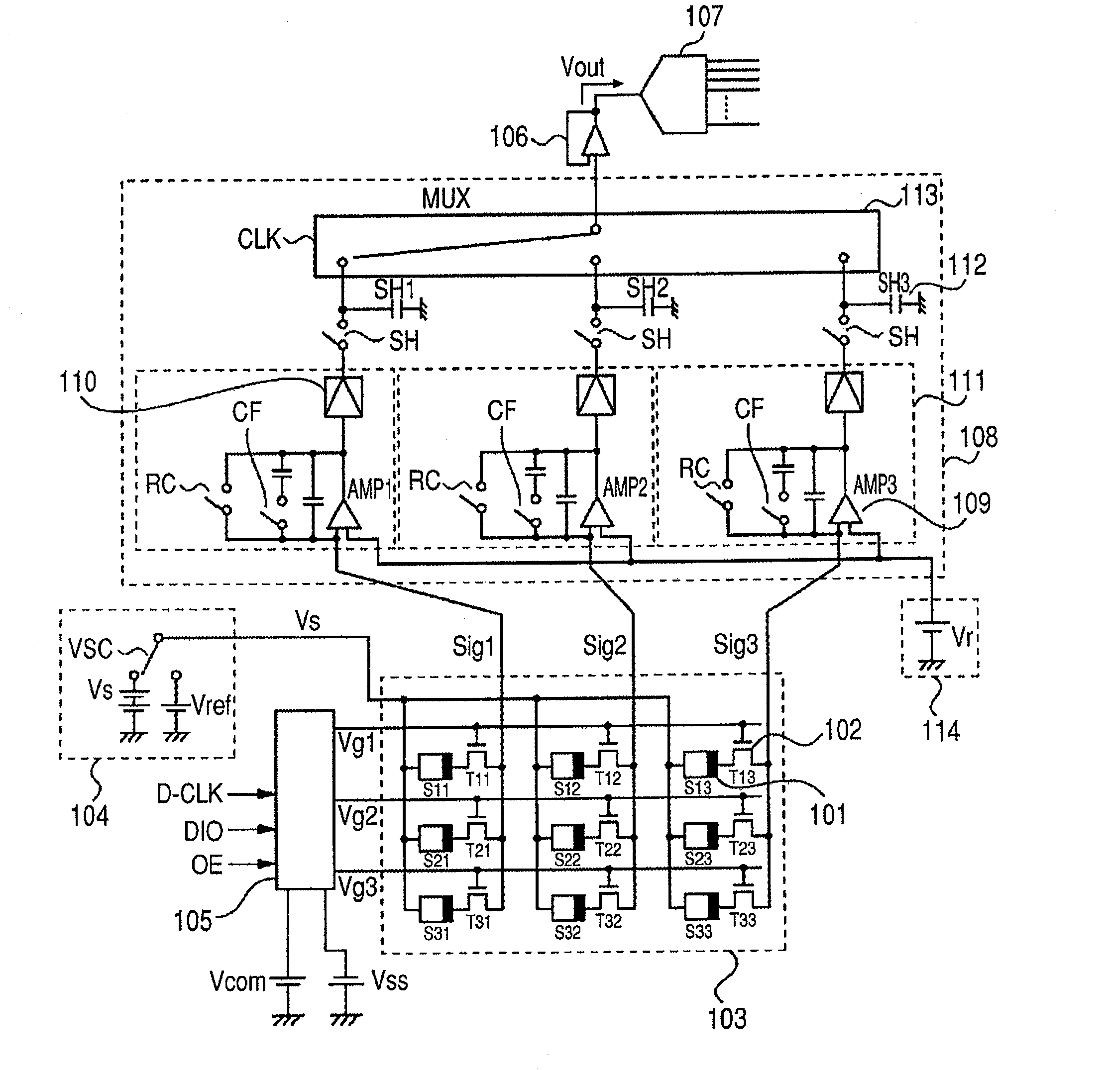
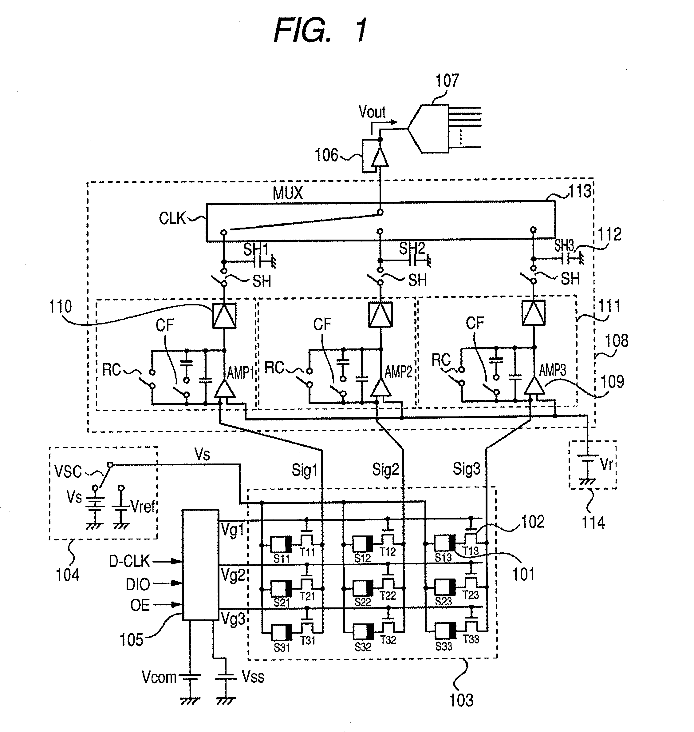
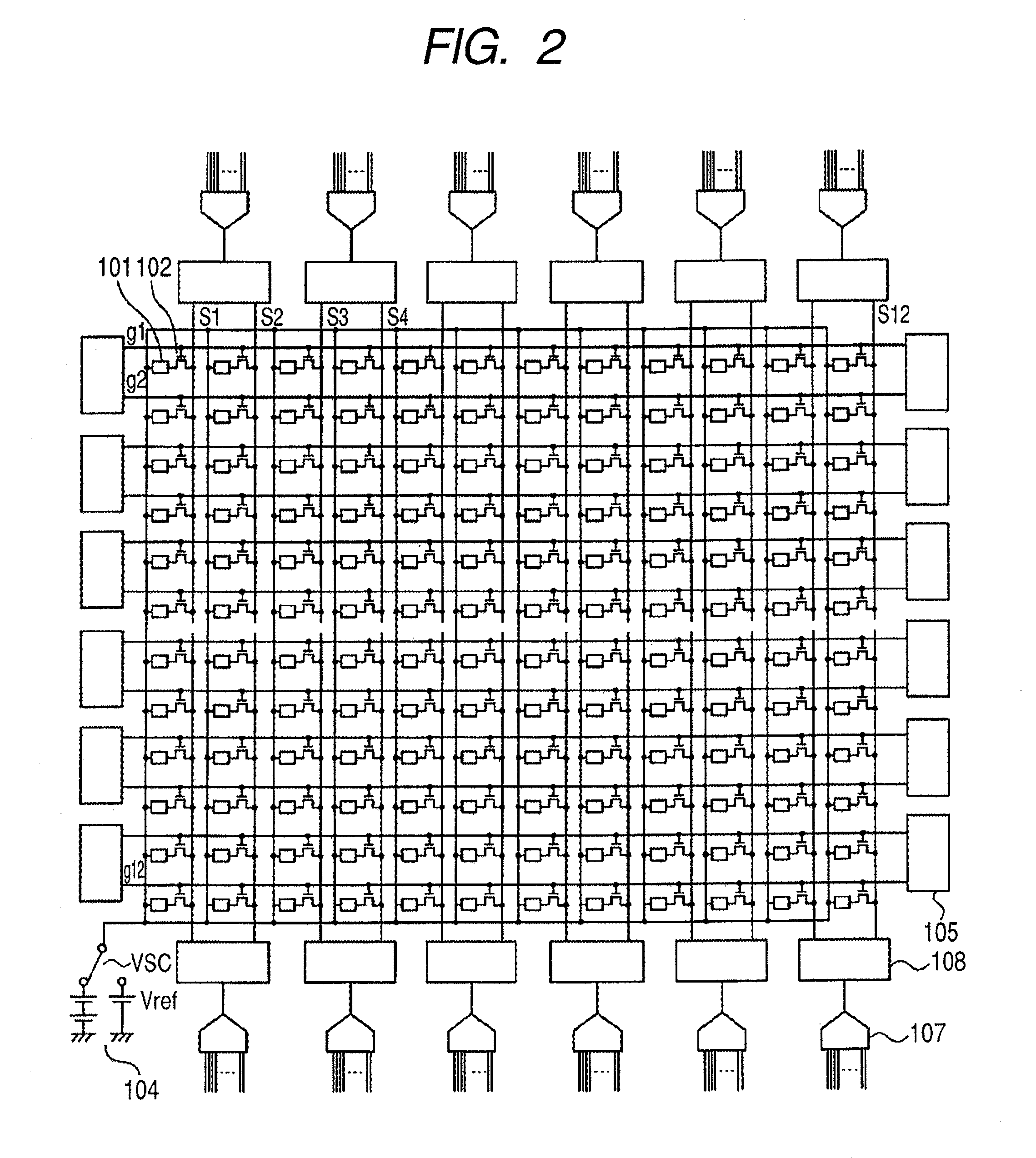
[0028]FIG. 1 is a schematic circuit diagram of an FPD used in the radiation imaging apparatus according to the present invention. In FIG. 1, the FPD includes a photoelectric conversion element 101 forming conversion elements for converting radiation into electric charge and a thin film transistor (TFT) 102 being a switching element for transferring an electric signal based on electric charge converted by the photoelectric conversion element 101. One pixel includes at least a pair of the photoelectric conversion element 101 and the TFT 102. The FPD further includes a two-dimensional area sensor 103 in which a plurality of pixels are two-dimensionally arranged in the row and the column direction. A bias power supply 104 supplies a bias required for photoelectric conversion to the photoelectric conversion element 101 and is connected to one of the electrodes of the photoelectric conversion element 101 through a bias wiring Vs. A drive circuit 105 controls the conduction state of TFTs 1...

second embodiment

[0060]The second embodiment related to the radiation imaging apparatus of the present invention is described using FIG. 10. FIG. 10 is a schematic flow chart illustrating the image capturing operation of the radiation imaging apparatus using the FPD in the present embodiment.

[0061]In the present embodiment, a read out operation is conducted twice every time X-rays are radiated, as is not the case with the first embodiment. The first read out operation of the two is such that X rays are radiated to read out the electric signals from the FPD based on X rays transmitted through the object. The second is to read out dark current and image lag components stored in the conversion element. Although a frame rate in this drive is lower than that in the drive described in the first embodiment, picture quality can be improved because image lag and dark current components can be removed in real time.

third embodiment

[0062]The following is a description of a radiation imaging system using the radiation imaging apparatus with the FPD according to the present invention with reference to the drawings.

[0063]FIGS. 11A and 11B are schematic diagrams describing a fluoroscopic system using the radiation imaging apparatus with the FPD according to the present invention.

[0064]FIG. 11A is a schematic diagram of a stationary radiation imaging apparatus fixed to the ceiling of a consulting room. FIG. 11B is a schematic diagram of a mobile radiation imaging apparatus. In FIGS. 11A and 11B, the radiation imaging system includes a radiation generating unit 801 for generating radiation such as X rays, flat panel detector (FPD) 802, holding unit 803 referred to as C-type arm for holding the radiation generating unit 801 and the flat panel detector 802, display unit 804 capable of displaying radiographic image information captured by the flat panel detector 802, bed 805 for placing thereon an object, carriage 806 ...


PUM


Abstract

An image apparatus capable of improving a frame rate to prevent resolution in the predetermined area from decreasing and forming image signals outside the predetermined area has an area sensor in which a plurality of pixels is arranged in a matrix, a drive circuit unit, a read out circuit unit and a processing unit processing signals transferred from the read out circuit unit. The drive circuit unit and the read out circuit unit perform a first operation in which signals are simultaneously read out from N pixels in a first area of the area sensor (where N is an integer equal to one or more) and a second operation in which signals are simultaneously read out from M pixels in a second area except the first area of the area sensor (where M is an integer equal to two or more and always greater than N), the first and second read out operations are continuously performed in one frame period, and a first and a second signal obtained by the first and the second read out operations are continuously transferred from the read out circuit unit to the processing unit.

Description

BACKGROUND OF THE INVENTION[0001]1. Field of the Invention[0002]The present invention relates to an imaging apparatus, a radiation imaging apparatus and a radiation imaging system, and more specifically, to an imaging apparatus used in a radiation imaging apparatus and radiation imaging system suitably used for still image radiographing such as plain radiographing and moving image radiographing such as fluoroscopy in medical diagnosis and an imaging apparatus used in a radiation imaging system. In the present invention, radiation includes not only alpha rays, beta rays and gamma rays being beams produced by particles (including photons) emitted by radioactive decay, but beams whose energy are nearly equal to or greater than the above, such as, for example, X rays, corpuscular rays and cosmic rays.[0003]2. Description of the Related Art[0004]In recent years, a radiation imaging apparatus using a flat panel detector (hereinafter, referred to as FPD) formed by a thin film semiconductor...

Claims


Application Information

Patent Timeline
Patent Type & Authority Patents(United States)
IPC IPC(8): H01L27/00A61B6/00H01L27/146H01L31/09H04N5/32H04N5/335H04N5/341H04N5/349H04N5/353H04N5/369H04N5/374H04N5/376
CPCH04N3/1562H04N5/343H04N5/347H04N5/374H04N5/376A61B6/503H04N5/32H04N25/42H04N25/443H04N25/445H04N25/46H04N25/74H04N25/76
Inventor YAGI, TOMOYUKIENDO, TADAOKAMESHIMA, TOSHIOTAKENAKA, KATSUROYOKOYAMA, KEIGO
Owner CANON KK
Why Eureka
Try Eureka