Image sensing apparatus and method having high and low resolution transfer modes

Inactive Publication Date: 2009-04-21
CANON KK
View PDF19 Cites 2 Cited by
  • Summary
  • Abstract
  • Description
  • Claims
  • Application Information

AI Technical Summary

Benefits of technology

[0023]Accordingly, an object of the present invention is to provide an image input apparatus and system and an image sending / receiving system in which settings can be made with ease and whereby low-resolution images such as digital moving images and high-resolution images such as still images can be transmitted to a host personal computer and videoconferencing can be carried out in cooperation with an application.
[0024]Another object of the present invention is to provide a system in which a changeover between the sensing and transfer of low-resolution images such as moving images and high-resolution images such as still images can be performed smoothly during image sensing and data transfer operations.

Problems solved by technology

However, a disadvantage is that a special integrated cable must be used.
This is a troublesome and time-consuming operation.
Accordingly, a drawback is that these systems do not take into account the handling of digital still images when they are transferred to the host personal computer 101.

Method used


Image

  • Image sensing apparatus and method having high and low resolution transfer modes
  • Image sensing apparatus and method having high and low resolution transfer modes
  • Image sensing apparatus and method having high and low resolution transfer modes

Examples


first embodiment

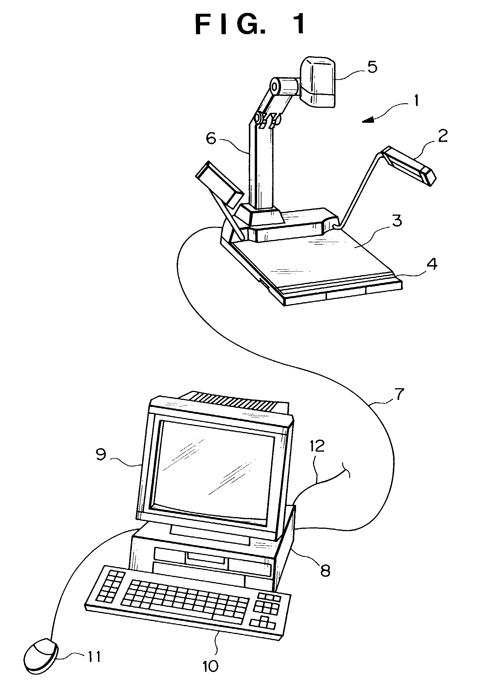
[0050]FIG. 1 is an external view showing the overall configuration of a desktop videoconference system according to a first embodiment of the present invention.

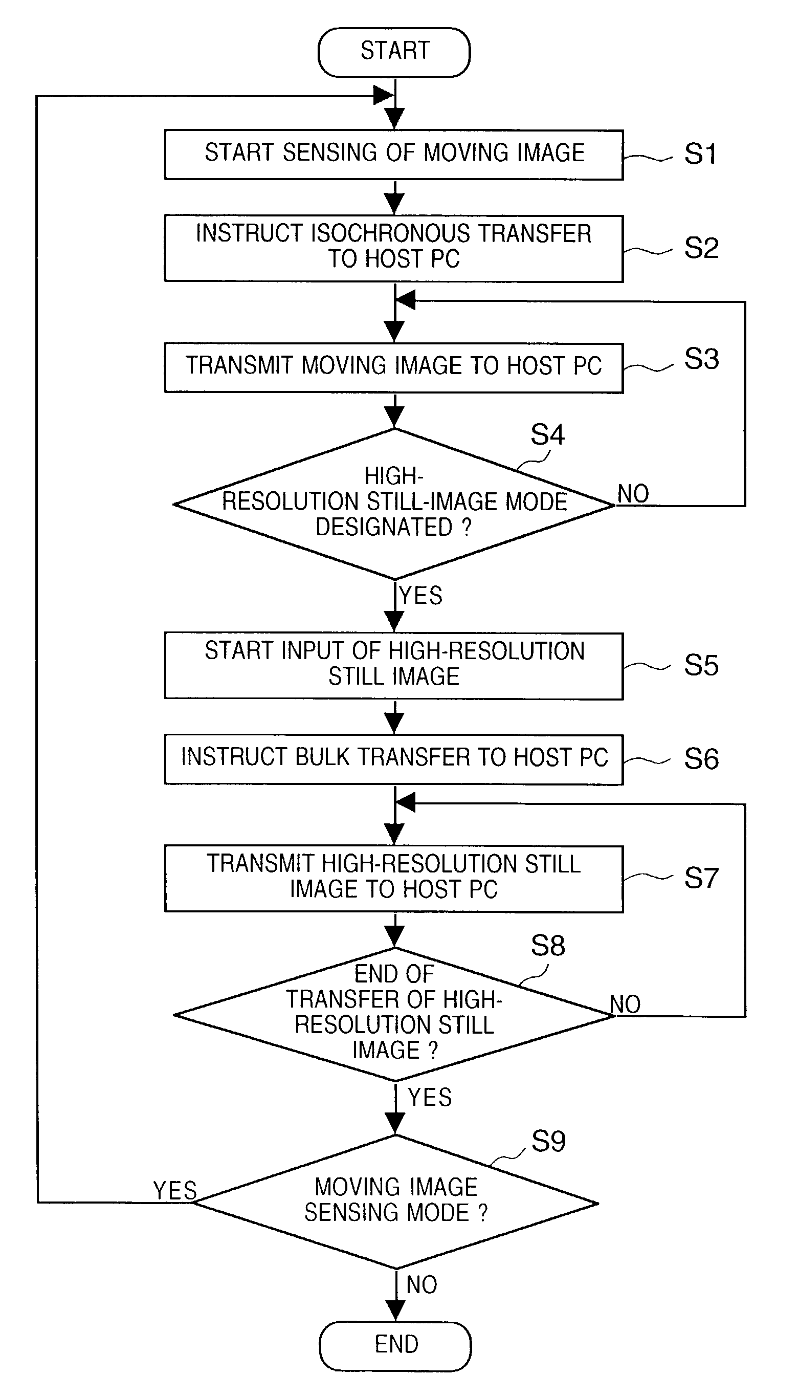
[0051]As shown in FIG. 1, the system includes a visualizer 1, which has an illuminating light 2, a document glass 3, a control panel 4 for operating the visualizer 1, an image data generating unit such as a freely rotatable camera head 5, and a camera head support 6 having a freely rotatable joint. The visualizer 1 makes it possible to switch between and output a moving image and a still image in response to instructions from the control panel 4 or host personal computer, as will be described later.

[0052]A USB cable 7 connects the visualizer 1 to a host personal computer 8, which has a monitor 9 serving as a display unit, a keyboard 10 and a mouse 11. A cable 12 is connected to an ISDN line, which is connected to a communications board 37 (see FIG. 2).

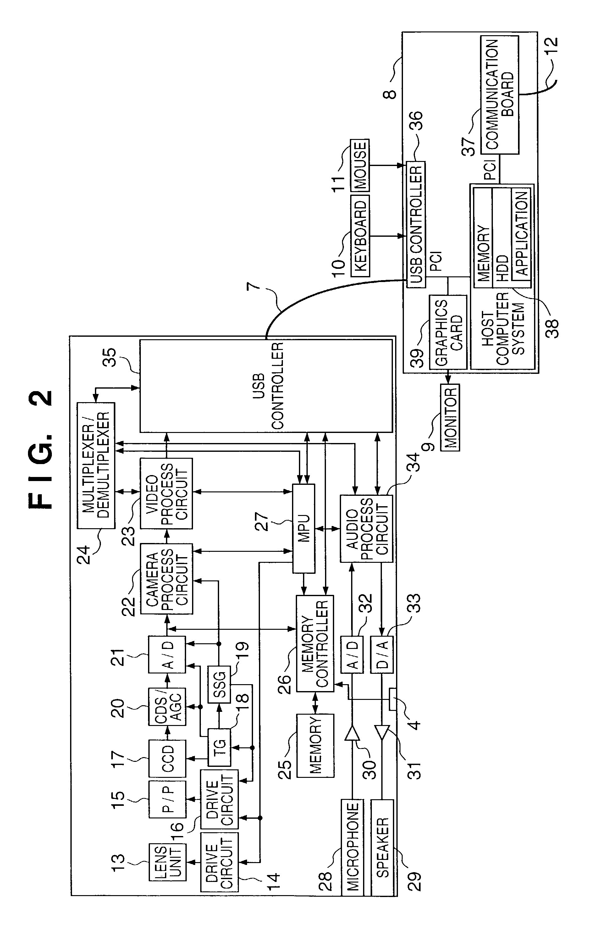
[0053]FIG. 2 is an overall block diagram showing the flow of various signal...

second embodiment

[0090]In the first embodiment, what is primarily described is transfer of a local image to the host personal computer 8 and display of the image on the monitor of the host personal computer 8 in order for an operation to performed using an application or the like.

[0091]In this embodiment, transfer of data from the visualizer 1 to the host personal computer 8 during a videoconference will be described.

[0092]The system configuration is the same as that of the system described in conjunction with FIGS. 1 and 2. During a videoconference, however, the image data processed by the camera process circuit 22 is subjected to compressing coding such as in accordance with H261 by the video process circuit 23 and the compressed coded data is transmitted to the multiplexer / demultiplexer 24. Data obtained by audio compression such as in accordance with G723 of ITU-T performed by the audio process circuit 34 and control data from the microprocessor are multiplexed and transferred to the host person...


PUM


Abstract

An image input apparatus includes an image data generating unit, a data transfer unit and a control unit. The image data generating unit generates high resolution image data if the image input apparatus is in a high-resolution image mode, and generates low resolution image data if the image input apparatus is in a low resolution image mode. The data transfer unit tranfers the high resolution image data to an external device in an asynchronous or bulk transfer mode, and transfers the low resolution image data to the external device in an isochronous transfer mode. The control unit changes the low-resolution image mode to the high-resolution image mode, if an instruction for selecting the high-resolution image mode is received from the external device during the transfer of the low resolution image data.

Description

CROSS REFERENCE TO RELATED APPLICATION[0001]This application is a division of application Ser. No. 09 / 246,169, filed Feb. 8, 1999, now U.S. Pat. No. 6,583,809.BACKGROUND OF THE INVENTION[0002]This invention relates to an image input apparatus, system, method and storage medium for inputting high-resolution and low-resolution images to a personal computer, for example. The invention further relates to an image sending / receiving system using a low-resolution / high-resolution image input apparatus.[0003]FIG. 13 is an external view of a videoconference system according to the prior art. The system includes a host personal computer 101 having a display 102, and a video camera unit 103, which is capable of being controlled by the host personal computer 101, for inputting moving images to the host personal computer 101. The video camera unit 103 is mounted on a pan head 110. An integrated cable 104 connects the host personal computer 101 to the video camera unit 103. The host personal compu...

Claims


Application Information

Patent Timeline
IPC IPC(8): H04N5/225G06F13/38G06F13/00G06T1/60H04L12/40H04L12/64H04N7/14
CPCH04L12/40058H04L12/40117H04N7/142H04N7/147H04N7/15
Inventor FUJIWARA, HIDEYUKI
Owner CANON KK
Why Eureka
Try Eureka