System and method for precision machining of high hardness gear teeth and splines

a high hardness, gear tooth technology, applied in the direction of gear teeth, manufacturing tools, mechanical equipment, etc., can solve the problems of inability to grind with a wheel type grinder, and inability to manufacture precision aerospace gear teeth and splines. , to achieve the effect of minimizing impact loading and the potential for fracture of cbn crystals, significant economic advantages, and minimizing tooth to tooth spacing errors

Active Publication Date: 2009-05-05
SIKORSKY AIRCRAFT CORP
View PDF23 Cites 4 Cited by
  • Summary
  • Abstract
  • Description
  • Claims
  • Application Information

AI Technical Summary

Benefits of technology

[0011]The hone tool may be driven with rotational and reciprocating synchronous teeth generating motion in which the hone tool reciprocates along the length of the teeth parallel to the centerline of the workpiece while the workpiece and hone tool rotate with synchronous motion. Typical of teeth geometry machining, there is a back-off stroke between the cut stroke and the return stroke. Alternatively, the hone tool is maintained in mesh with the workpiece teeth geometry during both the cut stroke and the return stroke to minimize impact loadings and the potential for fracture of the CBN crystals.
[0012]Applicant has proven the benefits of this process on production aerospace gears which were previously considered scrap. Such scrap reduction and salvage achieves significant economic advantages.
[0013]The present invention therefore provides a system and method to precisely machine aerospace quality gears and splines after a heat treat process which minimizes tooth to tooth spacing error, accumulated spacing error, lead error, involute error, concentricity error, roundness errors, pin size error or minor / major diameter errors to reduce scrap rates thereof.

Problems solved by technology

Some distortion is an inherent and inevitable result of heat treatment.
The distortion, however, is unacceptable on precision aerospace gears and splines when design tolerances are exceeded.
In many cases, however, it may not be possible to grind with a wheel type grinder due to part geometry limitations that may create an interference condition.
Lapping and honing methods have also been utilized but may have limited results because these machining methods may not provide the accuracy demanded in aerospace quality gears and splines.
This method tends to damage the involute form and may create an undesirable step condition in the root of the tooth.
Lapping also cannot correct tooth to tooth spacing error, accumulated spacing error, lead error, involute error, concentricity error, or roundness errors.
Typical computer numerically controlled honing machines are effectively utilized in some aerospace applications, but the machines may be cost prohibitive as such machines require vitrified type cutter tooling with diamond dressings.
Due to the limitations stated above, aerospace quality internal and external gears and splines are typically finish machined prior to the heat treat process with the expectation that the workpiece will not distort beyond desired design tolerances.
Although effective, some percentage of the workpieces will distort beyond design tolerances and are scrapped due to the lack of an effective rework process.

Method used


Image

  • System and method for precision machining of high hardness gear teeth and splines
  • System and method for precision machining of high hardness gear teeth and splines
  • System and method for precision machining of high hardness gear teeth and splines

Examples


Embodiment Construction

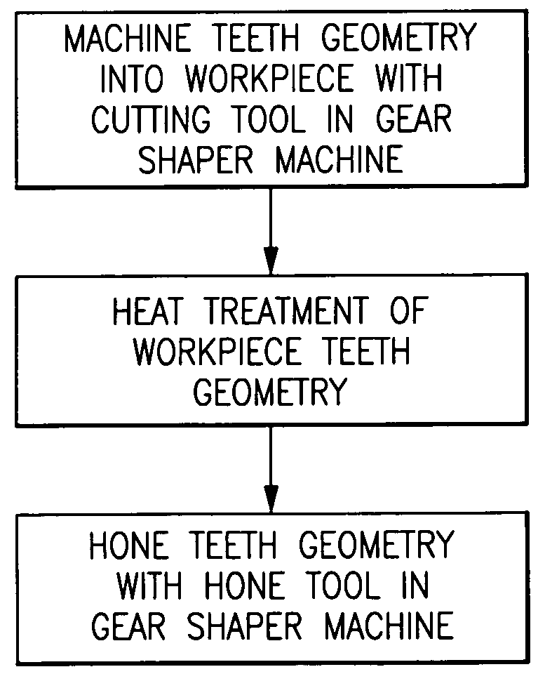
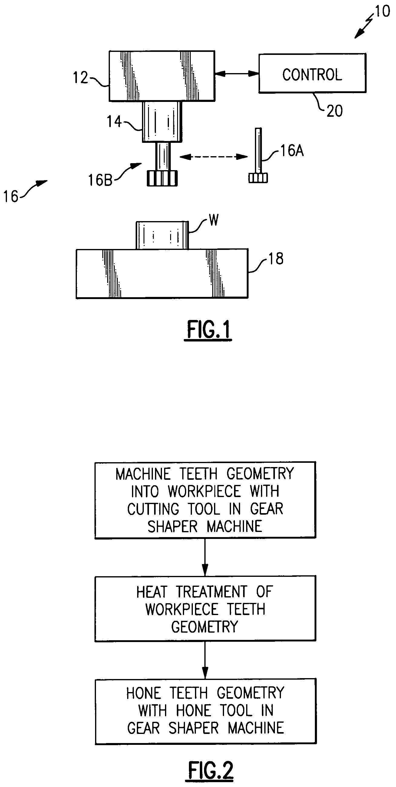
[0022]FIG. 1 illustrates a general block diagram of a gear shaper machine system 10 typical to the manufacture of aerospace quality internal and external gears and splines. It should be understood that although a gear with internal teeth geometry is disclosed in the illustrated embodiment, any workpiece which require the manufacture of teeth geometry typical of internal or external gears or splines will likewise benefit from the present invention.

[0023]The system 10 generally includes a machine head 12, a machine spindle 14, a replaceable tool 16, a workpiece fixture 18 and a controller 20 (illustrated schematically). Preferably, the system 10 utilizes a cutter tool 16A typical of a gear shaper machine that precisely generates the teeth geometry into the workpiece W in response to the controller 20 as generally understood. The controller 20 drives and maneuvers the cutter tool 16A to precisely generate the teeth geometry based on the relative motion between the workpiece and the cut...


PUM

PropertyMeasurementUnit
circumferenceaaaaaaaaaa
synchronous relative rotationaaaaaaaaaa
hardnessaaaaaaaaaa

Abstract

A gear shaper machine system drives and maneuvers a hone tool to generate teeth geometry in a manner the teeth were machined prior to a hardening process. After heat treatment, the hone tool is indexed to the teeth geometry spacing of the workpiece so as to divide the stock removal evenly between the drive and coast sides. The hone tool may be driven with rotational and reciprocating synchronous teeth generating motion in which the hone tool reciprocates along the length of the teeth parallel to the centerline of the workpiece while the workpiece and hone tool rotate with synchronous motion.

Description

BACKGROUND OF THE INVENTION[0001]The present application claims priority to U.S. Provisional Patent Application Ser. No. 60 / 660,424, filed 10 Mar. 2005.[0002]The present invention relates to the precise manufacture of precision gear teeth and splines, and more particularly to a system and method to precisely hone heat treated gears and splines with a high hardness utilizing a gear shaper machine with Cubic Boron Nitride (CBN) tooling.[0003]Machining is normally required on precision gear teeth after the heat treat process due to the distortion or warp induced on the workpiece by the heat associated with the heat treat process. Some distortion is an inherent and inevitable result of heat treatment. The distortion, however, is unacceptable on precision aerospace gears and splines when design tolerances are exceeded.[0004]One method for machining precision gears in the hard state after the heat treat process is grinding with an abrasive wheel type media such as aluminum oxide or Cubic ...

Claims


Application Information

Patent Timeline
Patent Type & Authority Patents(United States)
IPC IPC(8): B24B1/00
CPCB23F5/16B23F17/006B23F19/05Y10S451/90Y10T409/10477Y10T409/104293Y10T409/105883
Inventor BITTNER, EDWARD H.MITCHELL, JR., GEORGE D.TAYLOR, RONALD S.
Owner SIKORSKY AIRCRAFT CORP
Why Eureka
Try Eureka