Pressure sensitive conductive sheet and panel switch using same

a technology of conductive sheets and panel switches, applied in the direction of contact mechanisms, instruments, diagnostic recording/measuring, etc., can solve the problems of difficult to achieve total thickness reduction, and achieve the effect of reducing thickness, stable change of resistance value, and little fluctuation of resistance valu

Inactive Publication Date: 2009-05-05
PANASONIC CORP
View PDF11 Cites 44 Cited by
  • Summary
  • Abstract
  • Description
  • Claims
  • Application Information

AI Technical Summary

Benefits of technology

[0014]The present invention provides a pressure sensitive conductive sheet where the change in the resistance value is small, operation is possible without failure, and reduction in the thickness is possible, as well as a panel switch using the same.
[0015]The pressure sensitive conductive sheet according to the present invention is formed by forming a first resistor layer on the lower surface of a base in film form and forming and layering a second resistor layer in which particles of different particle diameters are dispersed on the lower surface of the first resistor layer. Thus, the second resistor layer, which is in uneven form due to the particles having different particle diameters, makes contact with fixed contacts or the like in accordance with the pressing force, and at the same time, the fixed contacts or the like are electrically connected via the second resistor layer and the first resistor layer. In this configuration, stable change in the resistance value with little fluctuation in the resistance value resulting from repeated operation can be gained, and at the same time, reduction in the thickness can be achieved, by forming the two resistor layers in such a manner that they are layered on the lower surface of the base.
[0017]As described above, according to the present invention, a pressure sensitive conductive sheet which makes operation possible without failure and makes reduction in the thickness possible, as well as a panel switch using the same, can be realized.

Problems solved by technology

In addition, it is also difficult to achieve total reduction in the thickness because a certain thickness is required.

Method used


Image

  • Pressure sensitive conductive sheet and panel switch using same
  • Pressure sensitive conductive sheet and panel switch using same
  • Pressure sensitive conductive sheet and panel switch using same

Examples


first embodiment

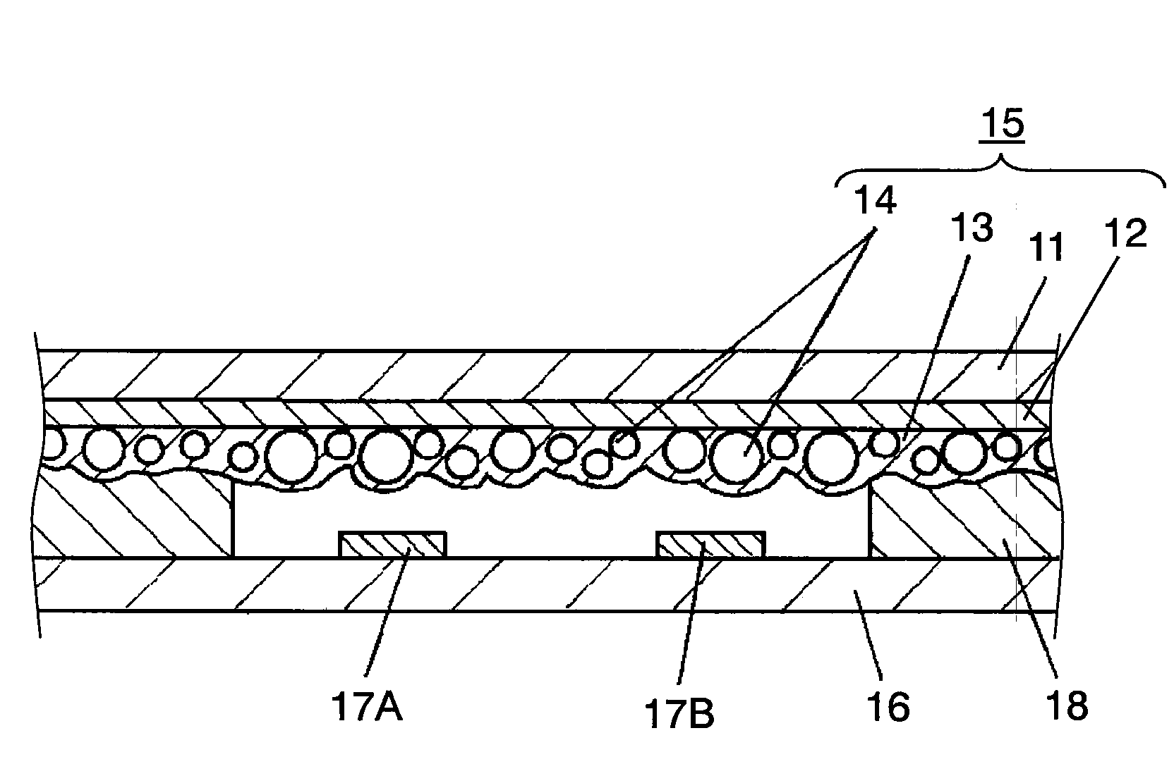
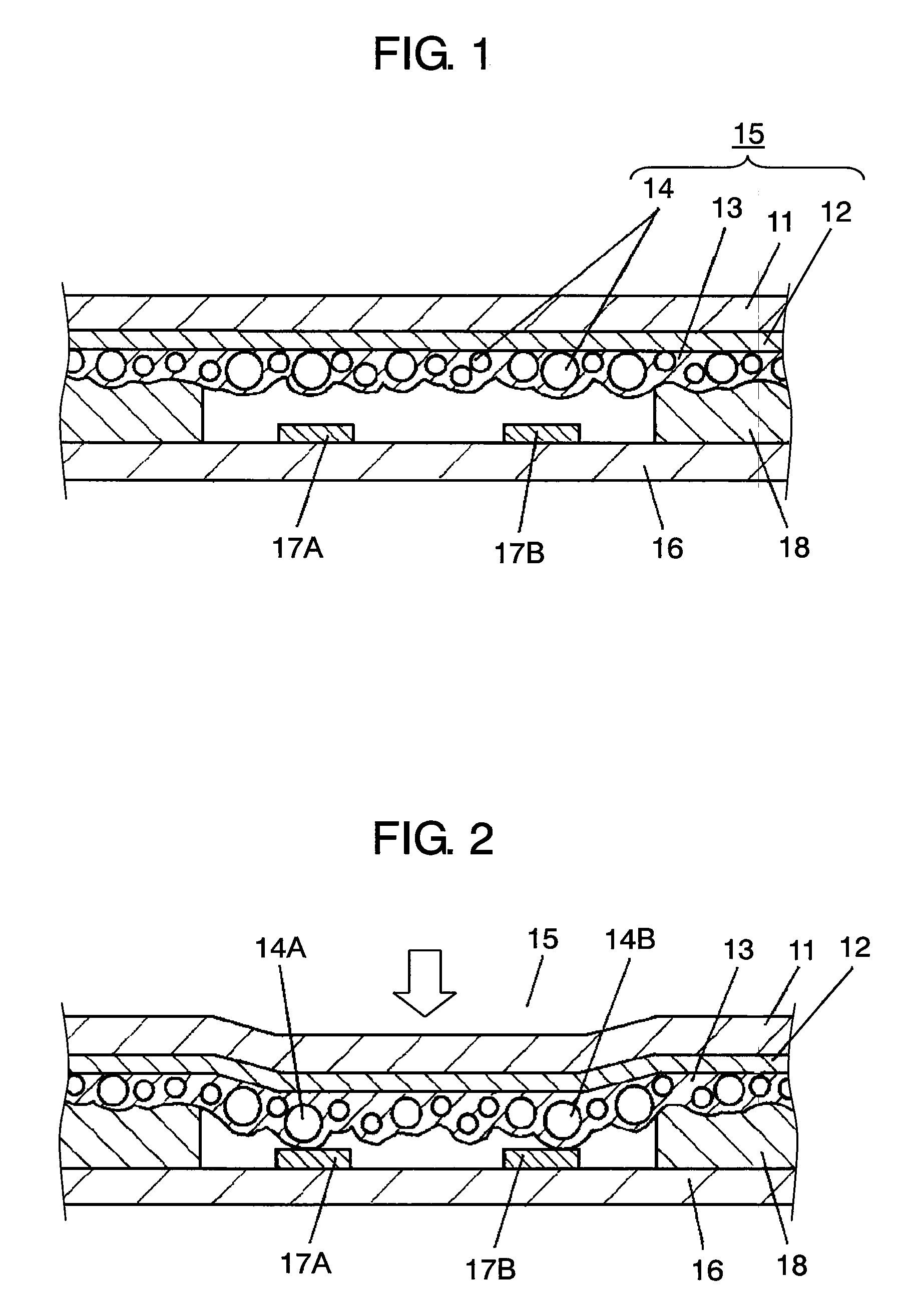
[0031]FIG. 1 is a cross sectional diagram showing a panel switch according to a first embodiment of the present invention. In FIG. 1, base 11 is in film form with a thickness of 25 μm to 200 μm and made of a polyethylene terephthalate, polycarbonate, polyimide or the like. First resistor layer 12 having a sheet resistance value of 0.5 kΩ to 30 kΩ / □ is formed of a synthetic resin, such as phenol, epoxy, phenoxy or fluorine rubber, in which a carbon powder is dispersed on the lower surface of base 11.

[0032]The second resistor layer is formed of a synthetic resin in which a carbon powder is dispersed so as to have a sheet resistance value of 50 kΩ to 5 MΩ / □ and a thickness of 1 μm to 50 μm, and layered on the lower surface of first resistor layer 12. Furthermore, 10 wt % to 80 wt % of particles 14 of urethane, glass or the like in spherical form with different particle diameters, ranging from 5 μm to 100 μm, are dispersed inside second resistor layer 13, and thus, pressure sensitive co...

second embodiment

[0046]The second embodiment is described below. Here, the same symbols are attached to portions having the same configuration as in the first embodiment, and the detailed descriptions thereof are omitted.

[0047]FIG. 6 is a cross sectional diagram showing a panel switch according to the second embodiment of the present invention. In FIG. 6, first resistor layer 12 having a sheet resistance value of 0.5 kΩ to 30 kΩ / □ is formed on the lower surface of base 11 in film form which is the same as in the first embodiment. In the present second embodiment, however, spacer 20 is formed from an insulating resin, such as polyester or epoxy, around the outer periphery of the center portion on the lower surface of first resistor layer 12.

[0048]In addition, second resistor layer 13 where particles 14 having a sheet resistance value of 50 kΩ to 5 MΩ / □ in which particles 14 are dispersed is formed and layered on the lower surface in the center portion of first resistor layer 12 and the lower surface ...


PUM

PropertyMeasurementUnit
sizeaaaaaaaaaa
thicknessaaaaaaaaaa
thicknessaaaaaaaaaa

Abstract

A first resistor layer is formed on the lower surface of a base in film form, and at the same time, a second resistor layer in which particles of different particle diameters are dispersed is formed and layered on the lower surface of the first resistor layer, and thus, a pressure sensitive conductive sheet is formed. In this configuration, the second resistor layer in uneven form makes contact with the fixed contacts in accordance with a pressing force so that electrical connection is made via the second resistor layer and the first resistor layer, and therefore, a thin panel switch with little fluctuation in the resistance value resulting from repeated operation where a stable resistance value can be gained can be realized.

Description

BACKGROUND OF THE INVENTION[0001]1. Field of the Invention[0002]The present invention relates to a pressure sensitive conductive sheet used mainly for the operation of various electronics, as well as a panel switch using the same.[0003]2. Description of the Related Art[0004]In recent years, as the functions and types of electronics, such as cellular phones and car navigation systems, have increased, various types of panel switches which make operation possible without failure have been in demand, as panel switches used for the operation of such electronics.[0005]These conventional panel switches are described with reference to FIGS. 8 and 9. Here, in the cross sectional diagram among these figures, the configuration is shown with the dimensions enlarged in the direction of the thickness for ease of understanding.[0006]FIG. 8 is a cross sectional diagram showing a conventional panel switch. In FIG. 8, pressure sensitive conductive sheet 1 is formed of base 2, for example of insulatin...

Claims


Application Information

Patent Timeline
Patent Type & Authority Patents(United States)
IPC IPC(8): H01H1/10
CPCG01L1/20H01H13/78H01H1/029H01H2201/036H01H2205/002H01H2227/012H01H2227/014H01H2229/002
Inventor TANABE, KOJIWATANABE, HIROTOSHI
Owner PANASONIC CORP
Why Eureka
Try Eureka