Scalable thermally efficient pump diode systems

a diode pump and thermal efficiency technology, applied in the direction of lasers, laser construction details, semiconductor lasers, etc., can solve the problems of significant energy loss, overheating of the diode pump, and significant energy loss, so as to improve the heat removal and/or excitation of the medium and enhance the heat removal system

Active Publication Date: 2009-05-05
D DIODE
View PDF5 Cites 11 Cited by
  • Summary
  • Abstract
  • Description
  • Claims
  • Application Information

AI Technical Summary

Benefits of technology

[0003]Incandescent lamps such as tungsten filament bulbs also may be used for pumping a laser. Such lamps generally emit a blackbody spectrum of radiation, which is a continuous spectrum that peaks at a particular wavelength depending on the temperature of the filament. Such a continuous spectrum may lead to substantial energy losses due to large amounts of radiation falling outside the absorption band of the laser. Although these losses can be minimized by carefully choosing the temperature of the filament such that the bulb's emission spectrum peaks near the center of the lasing medium's absorption band, and are further mitigated by the relatively low cost of the incandescent pump, they may be significant in many applications.
[0006]Unfortunately, despite the corrective attempts described above, problems of inefficiency, hot spots, large temperature gradients, and overheating still exist in diode pumped laser systems, especially systems that require high power. Thus, a need still exists for an improved diode pumped laser system, and components thereof, having increased thermal and packaging efficiency, more homogeneous excitation of a lasing medium, better-controlled temperature gradients, and / or more rapid conduction of heat away from the diode pumps. Improved thermal efficiency is especially lacking in the prior art. Inefficiency of removing heat from the diode bars results in limited power, reduced reliability, and increased system cost, weight, size, and power.SUMMARY
[0007]The present disclosure provides scalable, thermally efficient pump diode systems. These systems may include an arrangement of pump diodes and thermally conductive spacers mounted within a single indentation in a substrate or substrate clamps, so as to provide enhanced heat removal from the system. These systems also may include a plurality of such pump diode assemblies mounted, in a symmetric or partially symmetric arrangement, around a lasing medium in a diode pumped laser system, to improve heat removal and / or excitation of the medium.

Problems solved by technology

However, other emission peaks typically will lie outside this absorption spectrum, which can lead to significant energy losses.
Such a continuous spectrum may lead to substantial energy losses due to large amounts of radiation falling outside the absorption band of the laser.
Unfortunately, side pumping of a laser by one or more diode pumps may result in various undesirable effects, including inefficiency due to loss of diode energy, creation of isolated regions of excitement (“hot spots”) within the lasing medium, overheating of the diode pumps, uneven mechanical stress on the laser, and / or undesirably large temperature gradients between the diodes and the adjacent mounting surface, among others.
However, such systems still may suffer from thermal problems, such as overheating, at high-power outputs.
Unfortunately, despite the corrective attempts described above, problems of inefficiency, hot spots, large temperature gradients, and overheating still exist in diode pumped laser systems, especially systems that require high power.
Improved thermal efficiency is especially lacking in the prior art.
Inefficiency of removing heat from the diode bars results in limited power, reduced reliability, and increased system cost, weight, size, and power.

Method used


Image

  • Scalable thermally efficient pump diode systems
  • Scalable thermally efficient pump diode systems
  • Scalable thermally efficient pump diode systems

Examples


example 1

Pump Diode Assembly with Two-Component Substrate

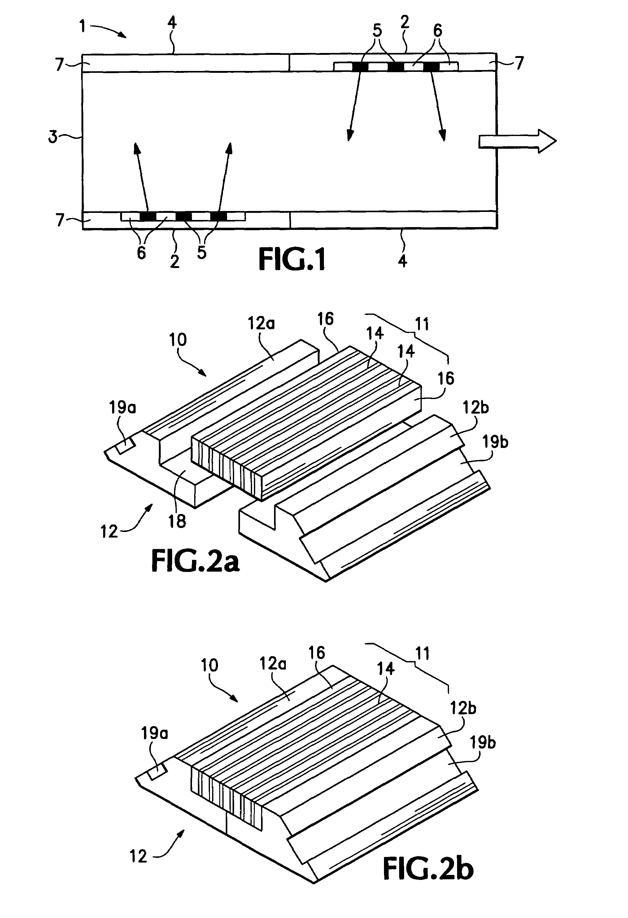
[0037]This example describes an exemplary pump diode assembly 10 having a “two-component substrate,” according to aspects of the present disclosure.

[0038]FIGS. 2a and 2b show diode assembly 10 in partially exploded and fully assembled states, respectively. The diode assembly includes a diode array 11 and a two-component substrate 12.

[0039]Diode array 11 includes a plurality of interspersed diode bars 14 and thermally conductive spacers 16. These components are disposed in an at least substantially parallel and alternating pattern, such that each diode bar is adjacent at least one spacer, and such that the diode bars and spacers collectively form a substantially planar right parallelepiped. Moreover, there typically will be one more spacer than diode bar, such that each diode bar is surrounded on both sides by a spacer, and such that the component at each end of the array is a spacer. In other embodiments, there may be one fewer spacers...

example 2

Pump Diode Assembly with Three-Component Substrate, Embodiment 1

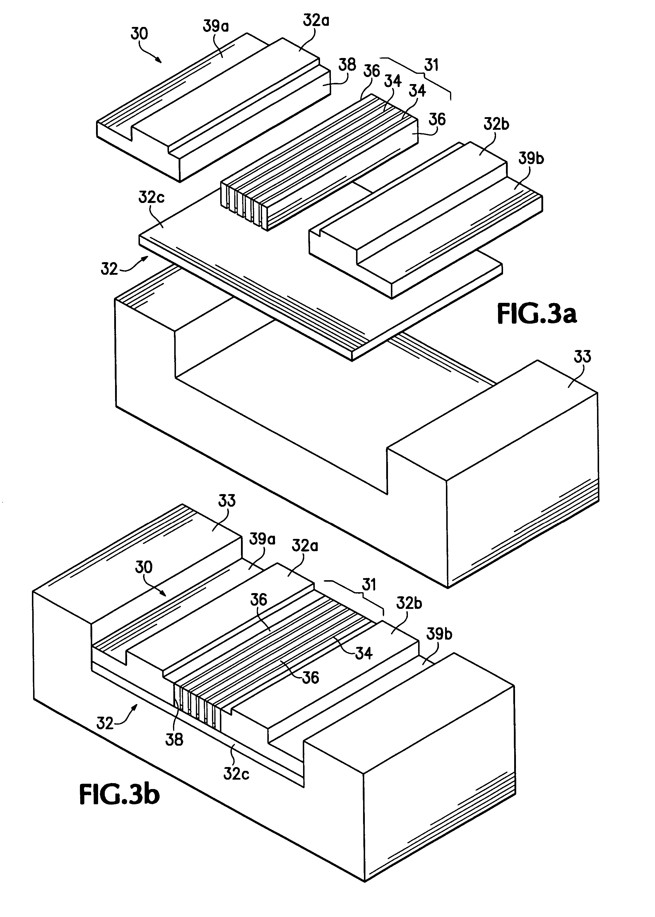
[0045]This example describes an exemplary pump diode assembly 30 having a “three-component substrate,” according to aspects of the present disclosure.

[0046]FIGS. 3a and 3b show diode assembly 30 in partially exploded and fully assembled states, respectively. The diode assembly includes a diode array 31, a three-component substrate 32, and an optional additional support member 33 (which may be considered an additional component of the substrate).

[0047]Diode array 31 includes a plurality of interspersed diode bars 34 and thermally conductive spacers 36. The diode array, including the bars and spacers, may be at least substantially as described above, for example, in Example 1.

[0048]Substrate 32 supports diode array 31 and optionally may be used to connect the diode array to a suitable laser. The substrate includes three components or base members 32a, 32b, and 32c, configured to fit together as shown to define an indentat...

example 3

Pump Diode Assembly with Three-Component Substrate, Embodiment 2

[0052]This example describes another exemplary pump diode assembly 30′ having a “three-component substrate,” according to aspects of the present disclosure.

[0053]FIGS. 3c and 3d show diode assembly 30′ in partially exploded and fully assembled states, respectively. The diode assembly includes a diode array 31′, a three-component substrate 32′, and an optional additional support member 33′. Diode assembly 30′ is similar to diode assembly 30, in Example 2. In particular, the diode arrays (e.g., 31, 34, and 36, and 31′, 34′, and 36′) and substrates (e.g., 32a-c, 38, and 39, and 32a′-c′, 38′, and 39′) may be at least substantially identical in the two embodiments. However, the optional additional support members (e.g., 33, and 33′) may differ between the two embodiments. For example, as pictured, member 33 is at least substantially U-shaped (with squared bends), whereas member 33′ is at least substantially planar. Member 33...


PUM


Abstract

Scalable, thermally efficient pump diode systems. These systems may include an arrangement of pump diodes and thermally conductive spacers mounted within a single indentation in a substrate or substrate clamps, so as to provide enhanced heat removal from the system. These systems also may include a plurality of such pump diode assemblies mounted, in a symmetric or partially symmetric arrangement, around a lasing medium in a diode pumped laser system, to improve heat removal and / or excitation of the medium.

Description

INTRODUCTION[0001]Lasers are devices that use a quantum mechanical effect, stimulated emission, to generate light. This light may be produced in continuous or pulsed modes and typically is intense, coherent, monochromatic, and directional. Lasers create light using a lasing medium capable of population inversion, a condition in which the rate of optical amplification—i.e., spontaneous photon emission followed by stimulated emission—exceeds the rate at which photons are absorbed by the medium. To attain population inversion, the atoms of the lasing medium generally must be excited by an external energy source. Excitation of a lasing medium typically begins with pumping by an external optical source, which may be tuned to excite one or more particular atomic transitions in the medium. In other words, the pump may be designed to output most or all of its light to match the absorption spectrum of the lasing medium, since any energy emitted by the pump and not absorbed by atoms within th...

Claims


Application Information

Patent Timeline
Patent Type & Authority Patents(United States)
IPC IPC(8): H01S3/09
CPCH01S3/0941H01S3/025H01S3/0405H01S3/042H01S3/0606H01S5/02264H01S5/024H01S5/02469H01S5/02476H01S5/4025H01S5/02365
Inventor GOKAY, CEMWILLIAMS, WILLIAM
Owner D DIODE
Why Eureka
Try Eureka