Optical receiver and optical reception method compatible with differential quadrature phase shift keying

a technology applied in the field of optical receiver and optical reception method, can solve the problems of deviating from the required value of delay interferometer, large optical receiver scale, and large size of optical receiver, and achieve the effect of low cost and stably demodulating

Inactive Publication Date: 2009-05-05
FUJITSU LTD
View PDF23 Cites 27 Cited by
  • Summary
  • Abstract
  • Description
  • Claims
  • Application Information

AI Technical Summary

Benefits of technology

[0016]The present invention has been accomplished in view of the above problems and has an object to provide a small sized optical receiver of low cost, capable of stably demodulating a signal light in accordance with a differential quadrature phase shift keying (DQPSK) system.
[0021]According to the above described optical receiver of the present invention, the processing of the DQPSK signal light, which has required dual system delay interferometers in the conventional configuration, can be realized by the common birefringent optical medium or the common delay interferometer. Therefore, an optical phase control can be easily performed and accordingly, it becomes possible to provide a small sized optical receiver which is stably operated in response to a temperature change.

Problems solved by technology

However, since the optical receiver having the conventional configuration as shown in FIG. 7 needs dual system delay interferometers each having the long optical path length, there is a problem in that the size of the optical receiver is enlarged.
In the case where such delay interferometers are realized by the optical waveguides formed on the silica substrates or the like, since it is necessary to arrange two optical waveguide substrates each having a large area, a large scale of the optical receiver is unavoidable.
Moreover, in the optical receiver having the conventional configuration, since it is necessary to precisely coincide the operating point (phase difference) of one of the delay interferometers with π / 4 and the operating point of the other delay interferometer with −π / 4, there is a problem in that a technology for controlling with high accuracy an optical phase within each of the delay interferometers and an optical phase between the delay interferometers is required.
To the above problems, in the case where the miniaturization of the optical receiver is attempted by integrating the two delay interferometers into one planner lightwave circuit (PLC) chip, there is a possibility that the temperature distribution or the like occurs in the PLC chip having a large area, and as a result, the delay time or the interference operating point in each of the delay interferometers is deviated from a required value.
In order to avoid such a possibility, the high accurate temperature designing or the high accurate packaging technology is needed, but may be an obstacle to the miniaturization and the low cost of the optical receiver.

Method used


Image

  • Optical receiver and optical reception method compatible with differential quadrature phase shift keying
  • Optical receiver and optical reception method compatible with differential quadrature phase shift keying
  • Optical receiver and optical reception method compatible with differential quadrature phase shift keying

Examples


first embodiment

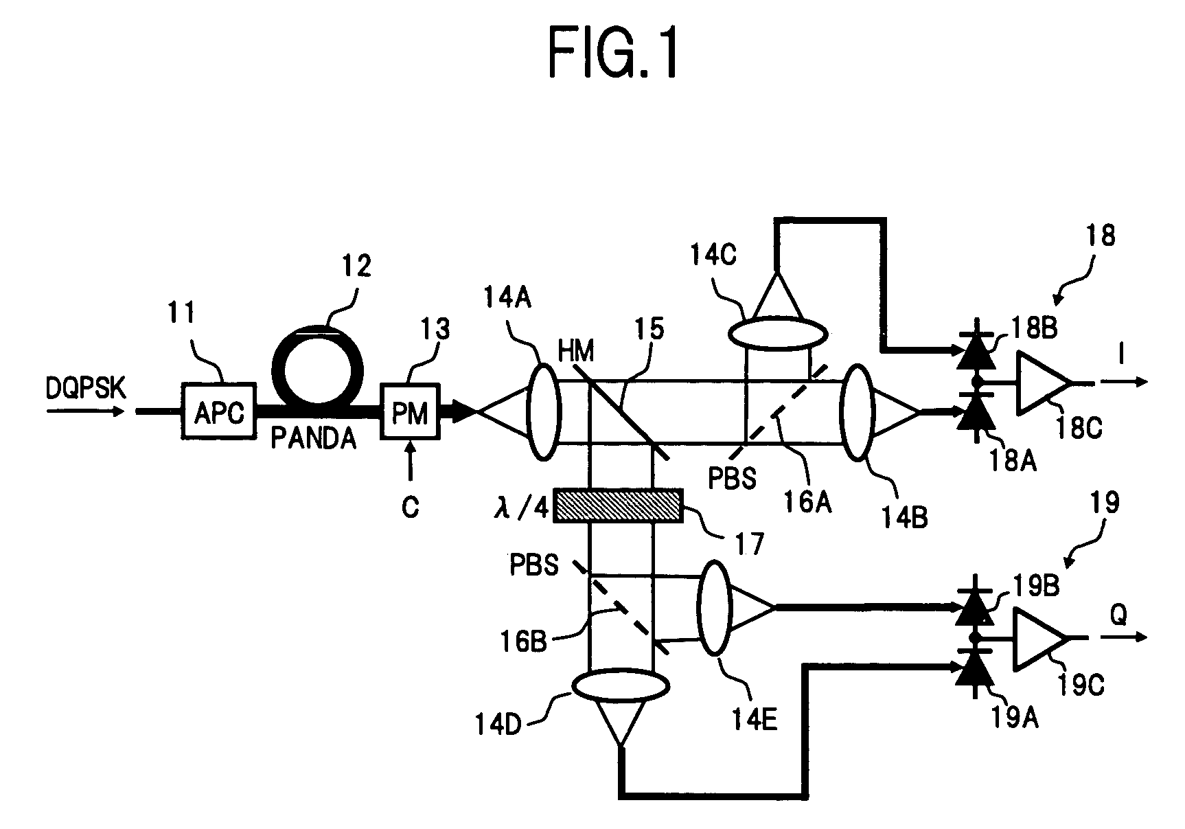
[0031]FIG. 1 is a block diagram showing a configuration of an optical receiver according to the present invention.

[0032]In FIG. 1, the optical receiver in the present embodiment comprises, for example, an automatic polarization controller (APC) 11 as a polarization converting section, a PANDA (Polarization-maintaining AND Absorption reducing) type fiber 12 as a birefringent optical medium, an optical phase modulator 13 as a delay time difference correcting section, collimator lenses 14A to 14E, a half mirror (HM) 15 as a branching section, polarization beam splitters (PBS) 16A and 16B as first and second polarization separating sections, a ¼ wave plate (π / 4) 17 as a birefringent amount difference generating section, and differential reception circuits 18 and 19 as first and second reception sections.

[0033]The automatic polarization controller 11 receives, at an input port thereof, a DQPSK signal light transmitted via an optical transmission path connected to the present optical rece...

second embodiment

[0044]Next, there will be described the present invention.

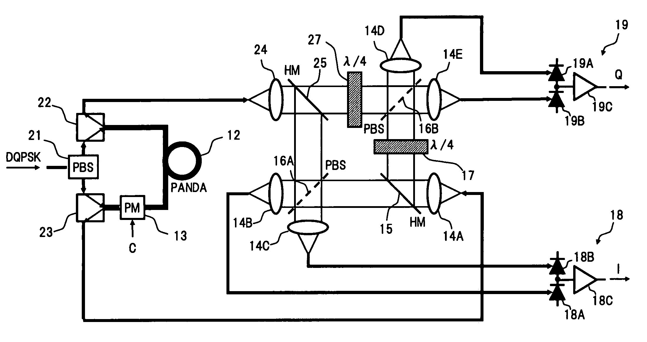
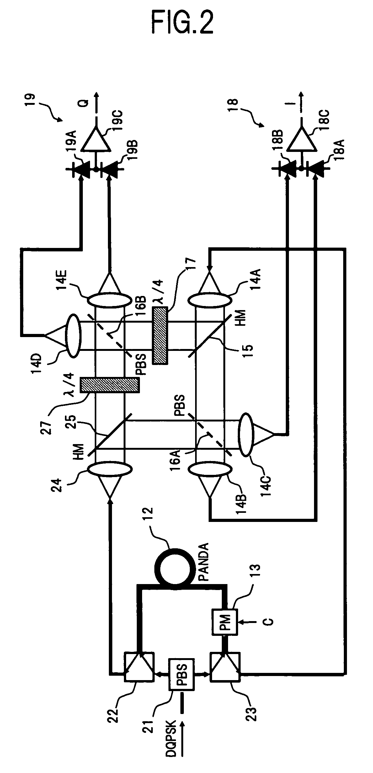
[0045]In the above first embodiment, there has been shown the configuration example in which the polarization state of the input light is controlled by the automatic polarization controller 11, so that the DQPSK signal light input to the optical receiver becomes the linearly polarized light inclined by 45° to the intrinsic axis of the PANDA type fiber 12. However, generally, the polarization state of the signal light which is propagated through the optical transmission path or the like to reach the optical receiver is arbitrarily changed at a high speed. Therefore, there is a problem in that the automatic polarization controller 11 needs to be operated at a high speed following the change in the polarization state. In the second embodiment, the description will be made on an application example of a so-called polarization diversity system, in which the DQPSK signal light in an arbitrary polarization state can be received with...

third embodiment

[0056]Next, there will be described the present invention.

[0057]FIG. 3 is a block diagram showing a configuration of an optical receiver according to the third embodiment.

[0058]In FIG. 3, the optical receiver in the present embodiment comprises, for example, an automatic polarization controller (APC) 31 as a polarization converting section, a planar lightwave circuit (PLC) 32 in which one delay interference section 35 and two polarization separating sections 36A and 36B, are formed on the same substrate, and differential reception circuits 33 and 34 as first and second reception sections.

[0059]The automatic polarization controller 31 is capable of arbitrarily changing the polarization state of the DQPSK signal light input to the present optical receiver, similarly to the automatic polarization controller 11 in the first embodiment. Here, this automatic polarization controller 31 monitors therein the polarization state of the DQPSK signal light input to an input port thereof to autom...


PUM

PropertyMeasurementUnit
optical path lengthaaaaaaaaaa
differential currentsaaaaaaaaaa

Abstract

In an optical receiver according to the present invention, an input signal light subjected to the differential quadrature phase shift keying (DQPSK) is incident on a PANDA type fiber in a linearly polarized state by 45°, so that a delay time difference corresponding to one symbol is generated between orthogonal polarization components in the DQPSK signal light, and then, the signal light is branched by a half mirror into two, to be sent to first and second paths respectively, thereby giving, by a ¼ wave plate disposed on one of the paths, a relative birefringent amount difference of π / 2 between the lights propagated through the respective paths. Then, each of the lights propagated through the first and second paths is separated into two orthogonal polarization components by a polarization beam splitter, and the respective polarization components are received by a differential reception circuit so that in-phase components and quadrature components in the DQPSK signal are demodulated. Thus, a small sized and low cost optical receiver capable of stably demodulating the DQPSK signal is provided.

Description

BACKGROUND OF THE INVENTION[0001]1. Field of the Invention[0002]The present invention relates to an optical receiver and an optical reception method, for demodulating a signal light subjected to the differential quadrature phase shift keying, and in particular, to a technology for realizing a stably operated optical receiver of a small size.[0003]2. Description of the Related Art[0004]In recent years, as a technology enabling the high bit rate optical transmission at 40 Gb / s or higher, there has been noticed an optical modulation system, such as a differential phase shift keying (DPSK) system, a differential quadrature phase shift keying (DQPSK) system or the like. The DQPSK system has a more excellent characteristic in terms of the long distance transmission, the dense multiplexing / large capacity, and the design performance, usability and the like, in comparison with a known optical modulation system, such as, a typical non-return to zero (NRZ) modulation system, a CS-RZ modulation...

Claims


Application Information

Patent Timeline
Patent Type & Authority Patents(United States)
IPC IPC(8): H04B10/00H04B10/40G02F2/00H04B10/25H04B10/50H04B10/516H04B10/548H04B10/60H04B10/61H04B10/67H04B10/69
CPCH04B10/532H04B10/61
Inventor HOSHIDA, TAKESHI
Owner FUJITSU LTD
Why Eureka
Try Eureka