Heating apparatus with electrode for the conductive heating of melts

a technology of conductive resistance and heating apparatus, which is applied in the direction of ohmic resistance electrodes, glass blowing apparatus, glass shaping apparatus, etc., can solve the problems of high energy loss, no known contact material which can be used in practice, and the inability to select any desired high temperature in the melt, etc., to achieve the effect of improving cooling

Inactive Publication Date: 2009-05-12
SCHOTT AG
View PDF2 Cites 2 Cited by
  • Summary
  • Abstract
  • Description
  • Claims
  • Application Information

AI Technical Summary

Benefits of technology

[0021]On the other hand, an apparatus according to the invention can also be operated in such a way that the heat flux passing through the electrode on account of temperature gradients within the melt is compensated for, so that a uniform surface temperature is achieved on the melt contact material of the electrode. This allows the cooling power to be reduced to the required minimum and also allows the heating power to be reduced, thereby considerably improving the overall energy balance. Moreover, the surface temperature can safely be kept close to the material-dependent limits. By way of example, a platinum electrode should not be heated to over 1 650° C. even briefly, and in long-term operation should not be heated to over 1 550° C. The apparatus according to the invention allows operation in which the temperature of virtually the entire surface of the melt contact material of the electrode can be uniformly kept close to this limit. By contrast, by reducing the cooling power and implementing a surface of the melt contact material which is as uniformly hot as possible, it is in this way possible to achieve a high peak temperature in the melt which is well above the temperature of the surface of the melt contact material. In a manner which is in accordance with the invention and surprising to the person skilled in the art, the melt temperature in the melt can for the first time be more than 200° C. above the highest temperature at the electrode surface. This correspondingly also improves and accelerates the refining of the melt. However, the invention also provides advantages even if the temperature of regions of the melt is only 50° C., 100° C. or 150° C. above the temperature of the electrode surface.
[0055]The device for heating the electrode may also comprise a device for heating the cooling fluid. This makes it possible, for example, to heat the melt contact surface of the electrode to a temperature above the dew point. This is advantageous in particular if precipitation of moisture, as occurs, for example, when using fossil fuels before initial heating or preheating when starting up, is to be prevented.

Problems solved by technology

However, it is impossible to select any desired high temperatures in the melt, since the temperature which can be set is subject to restrictions in terms of the finite thermal stability of the components of the melting apparatus.
In particular, there are no known contact materials which can be used in practice and have a long-term stability at temperatures above 1 700° C.
However, the cooled wall parts cause high energy losses, which have to be compensated for by heating again.
However, radiofrequency heating is not suitable for all types of glass, since the melts have to have a certain minimum conductivity.
For example, the method is unsuitable for melt conductivities lower than 0.01 Ω−1 cm−1.
However, the process stability of radiofrequency heating becomes so poor even at conductivities below approximately 0.1 Ω−1 cm−1 that this technique is of only limited use or is scarcely viable in these cases.
On the other hand, glasses which contain little if any alkali metal often have only a poor conductivity.
However, in particular glasses of this type are often special technical-grade glasses, in which a particularly high purity and absence of bubbles is important, yet these glasses can only be treated with difficulty by radiofrequency heating, on account of their poor conductivity.
However, since heating of the melt also presents a risk of damage to the platinum electrode, the coolant supplied will generally effect cooling which maintains a safe thermal distance below the temperatures at which the platinum can be damaged.
The additional heating power is absorbed again by an increased cooling power, and the thermal safety margin represents an extremely unsatisfactory overall energy balance when using conventional cooled electrodes.
Furthermore, in the event of uncontrollable and excessive cooling of the conventional electrodes, there is a risk of the conductive heating being impossible to start, on account of a high transfer resistance between electrode and melt, caused by glass frozen onto the electrode.
Furthermore, the local cooling power on the surface of these electrodes is substantially predetermined by the arrangement of the cooling passages and by the electrode geometry, and therefore cannot be adapted to the external conditions.

Method used


Image

  • Heating apparatus with electrode for the conductive heating of melts
  • Heating apparatus with electrode for the conductive heating of melts
  • Heating apparatus with electrode for the conductive heating of melts

Examples


first embodiment

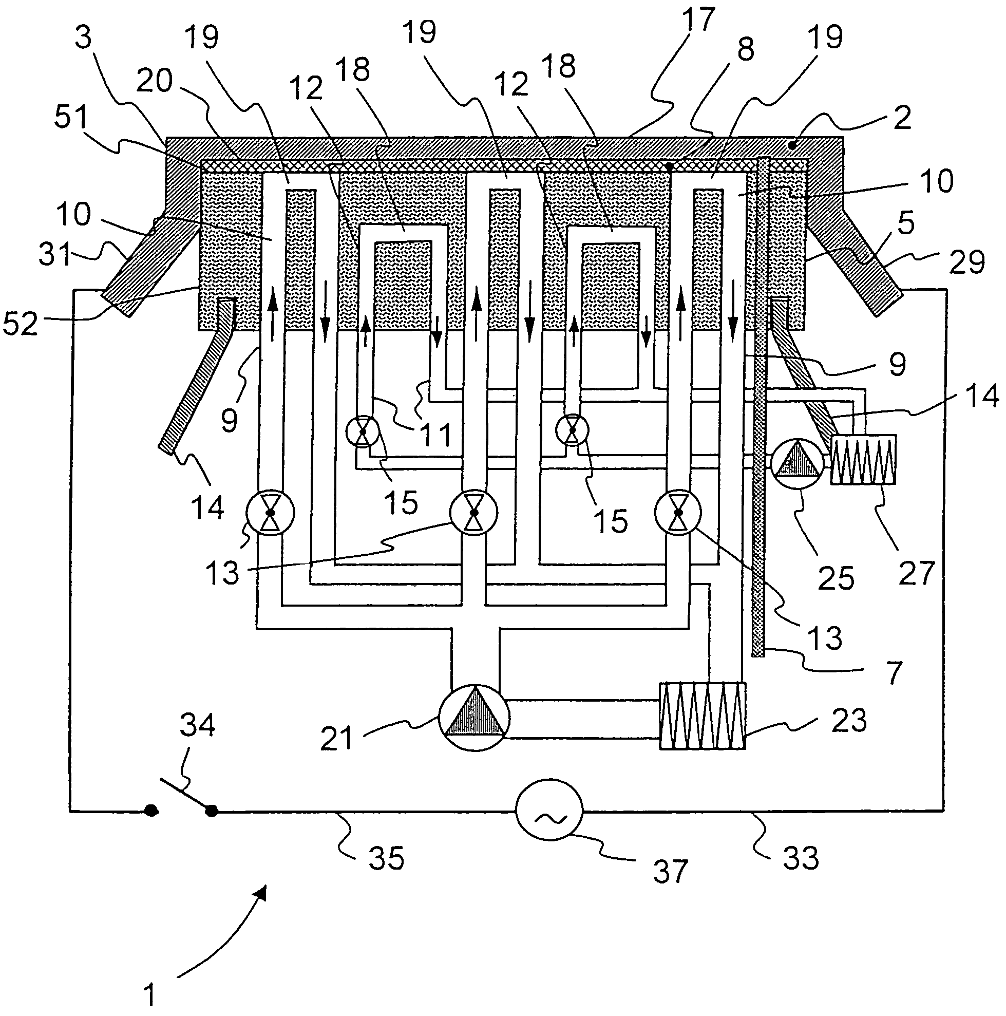
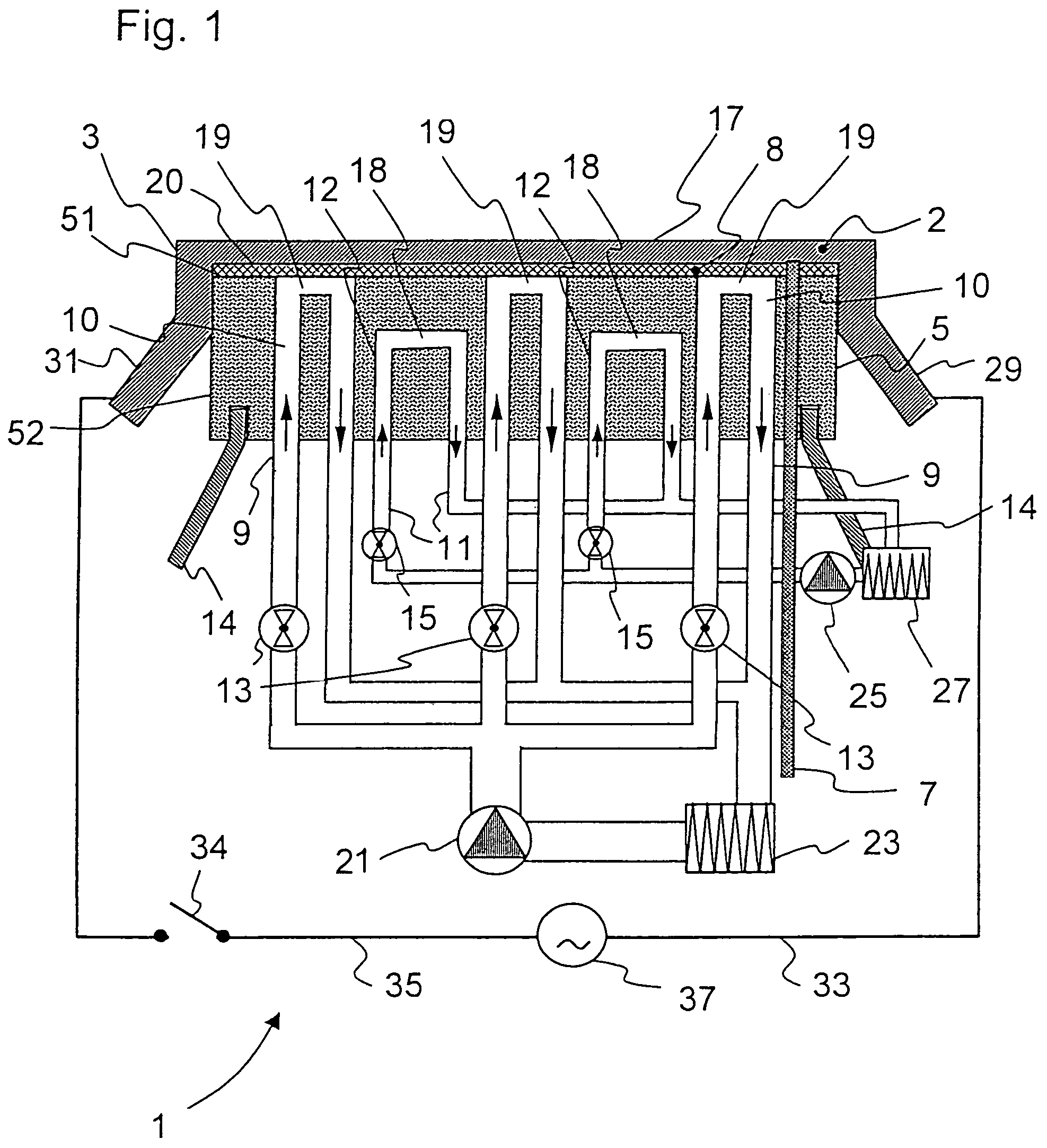
[0068]FIG. 1 shows the invention, in which the electrode 3 includes a melt contact material 2 comprising a metallic material, for example a refractory metal, such as tungsten, molybdenum and / or platinum, rhodium, iridium, as well as alloys thereof. The melt contact material 2 has been applied to a refractory material 8 or an electrically conductive ceramic, such as for example an SnO2 ceramic. The supporting apparatus 5 has a multiplicity of connections 9 which are connected to fluid-conducting passages 10 in the interior of the supporting apparatus, with the connections 9, as well as the fluid-conducting passages 10 connected to them, forming parts of a first cooling system.

[0069]Moreover, the supporting apparatus 5 has a multiplicity of further connections 11, which are likewise connected to fluid-conducting passages 12 in the interior of the supporting apparatus. These connections 11 and the fluid-conducting passages 12 connected to them form part of a further cooling system.

[007...

second embodiment

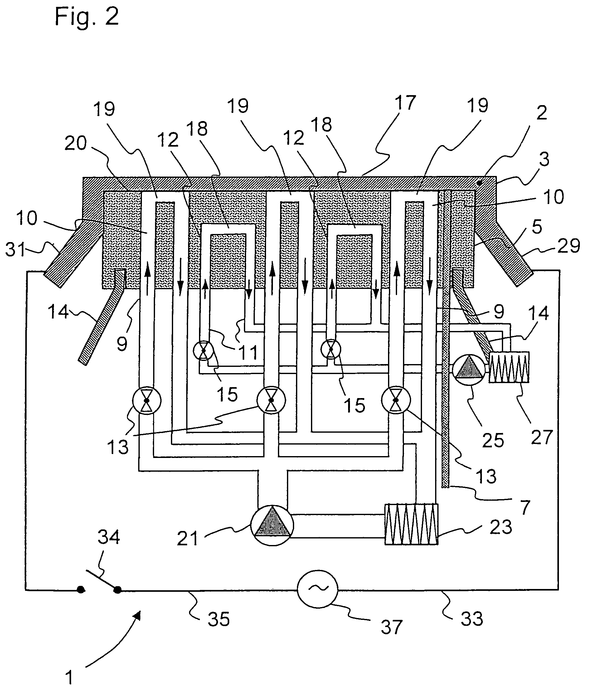
[0083]FIG. 2 shows the invention, in which the supporting apparatus 5 is not constructed in sandwich form. In this embodiment, a section 19 of the fluid-conducting passages 10 of the first cooling system likewise extends along the side 20 of the supporting apparatus 5 against which the electrode 3 bears. In this embodiment, the sections 19 are open directly toward the electrode 3. This produces direct contact between the coolant and the electrode 3, thereby achieving particularly successful and quickly controllable cooling. A heat transfer barrier, as is formed between two layers in a sandwich structure of the supporting apparatus, is also avoided.

[0084]However, in this case the melt contact material 2 of the electrode 3 must be sufficiently strong, even at the high temperatures of use, to prevent deformation or even cracking-open of the melt contact material 2, which is unsupported in the region of the sections 19, as a result of the hydrostatic pressure of the melt. By way of exam...


PUM

PropertyMeasurementUnit
pressureaaaaaaaaaa
temperaturesaaaaaaaaaa
temperatureaaaaaaaaaa

Abstract

A heating apparatus for the conductive heating of melts, in particular for the rapid melting-down, refining and / or conditioning of melts, is provided. The heating apparatus includes at least one electrode, as well as a first cooling system with a cooling power, which can be set and / or controlled variably.

Description

[0001]This application is a 371 of PCT / EP03 / 13352 filed on 27 Nov. 2003.BACKGROUND OF THE INVENTION[0002]1. Field of the Invention[0003]The invention relates to a heating apparatus for the conductive resistance heating of melts, in particular for the rapid melting-down of batch and / or for the refining and / or conditioning of melts, which comprises at least one electrode for the conductive heating of melts, in particular a cooled electrode for the conductive heating of melts.[0004]2. Description of Related Art[0005]The conductive heating of melts is used, inter alia, in the refining of glass melts. During refining, bubbles are expelled from the glass melt, preferably by adding special refining agents. To enable the bubbles to be expelled, it is desirable for the viscosity of the melt to be as low as possible. This is generally achieved by high temperatures being set in a refining zone of the melt. However, it is impossible to select any desired high temperatures in the melt, since the...

Claims


Application Information

Patent Timeline
Patent Type & Authority Patents(United States)
IPC IPC(8): C03B9/38C03B5/027C03B5/03C03B5/235C03B5/42C03B5/44H05B3/03
CPCC03B5/027C03B5/03C03B5/235C03B5/42C03B5/44H05B3/03C03B2211/70Y02P40/57
Inventor EICHHOLZ, RAINERRAEKE, GUIDOOHMSTEDE, VOLKERWEIDMANN, GUNTERLENTES, FRANK-THOMASSTELLE, THOMASSCHAEFER, ERNST-WALTERROEMER, HILDEGARDSCHOLLMAYER, JOERGHUNNIUS, HOLGERDRUSCHKE, FRANK-JURGEN
Owner SCHOTT AG
Why Eureka
Try Eureka