

Texture control of thin film layers prepared via laser induced thermal imaging
a technology of thermal imaging and texture control, applied in thermography, instruments, photosensitive materials, etc., can solve the problems of slow image recording speed (milliseconds), size limitations of printheads, and thermal printheads as energy sources
- Summary
- Abstract
- Description
- Claims
- Application Information
AI Technical Summary
Benefits of technology
Problems solved by technology
Method used
Image

Examples
example 1
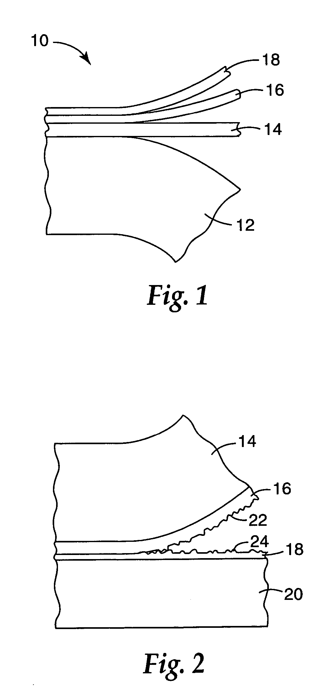
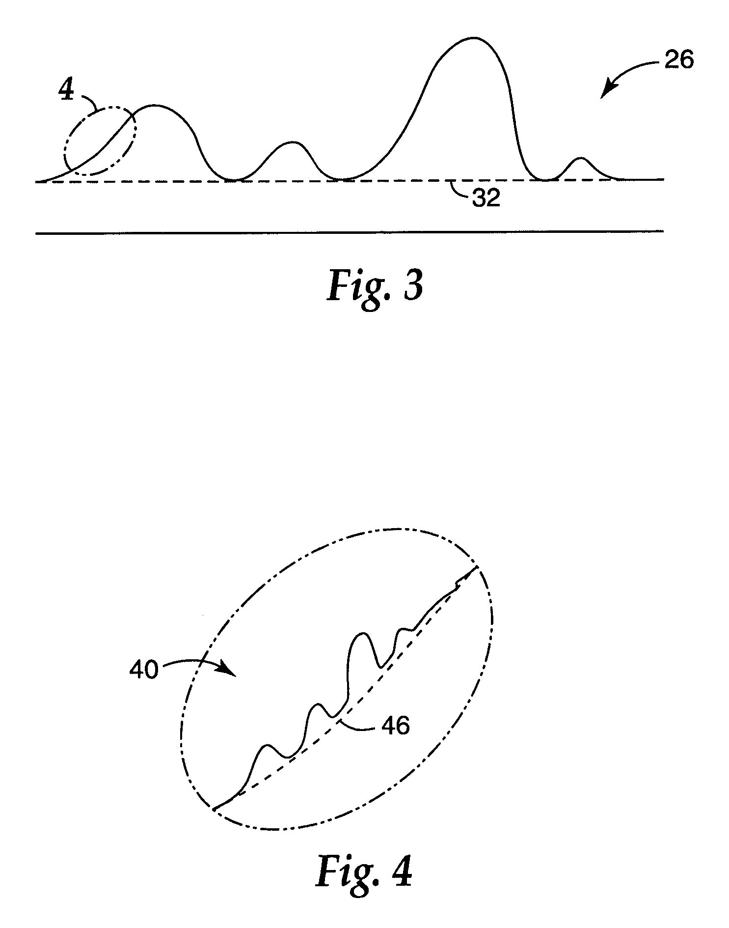
f Donor Surface Texture
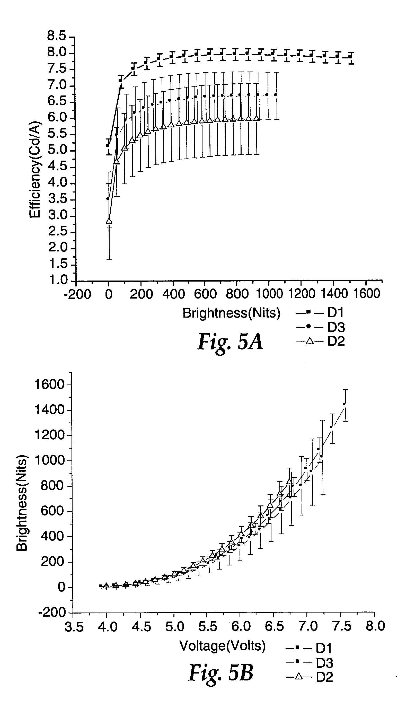
[0110]In preparing a small molecule device stack, transferring the emissive layer can be accomplished with donors of varying roughness. The roughness of the donor, prior to imaging, can impact the transfer layer roughness after having been transferred, which can impact the efficiency of the device. The process and materials used to build LITI devices are described below.
[0111]Receptor substrates were prepared by using 0.7 mm thick glass with photolithography-patterned ITO (Indium tin oxide) as the substrate. The substrate was spin coated with Baytron P VP CH8000 (H.C. Starck, Newton, Mass.) in order to achieve a dry thickness of approximately 60 nm and then heated to 200° C. for 5 minutes in a nitrogen purged oven. The coated substrate was then spin coated with a solution of HTM-001 (a hole transporting polymer from Covion Organic Semiconductors GmbH, Frankfurt, Germany), and toluene while in an argon purged glove box to achieve a dry thickness of approximatel...
example 2
f Transfer Layer Roughness with an Interlayer Having a Different Texture
[0125]In this example, smooth donors were prepared by depositing a smooth inorganic layer on the surface of a typical LTHC / IL donor construction. Modification of the surface chemistry can be advantageous to control the release of the transfer layer from the donor after patterning, as well as the surface texture of the transfer layer. The process and materials used to build LITI devices are described below.
[0126]Receptor substrates were prepared by using 0.7 mm thick glass with photolithography-patterned ITO (Indium tin oxide) as the substrate. The substrate was spin coated with Baytron P VP CH8000 (H.C. Starck, Newton, Mass.) in order to achieve a dry thickness of approximately 60 nm and then heated to 200° C. for 5 minutes in a nitrogen purged oven. The coated substrate was then spin coated with a solution of HTM-001 (a hole transporting polymer from Covion Organic Semiconductors GmbH, Frankfurt, Germany), and ...
example 3
f Donor Surface Texture by Sheeting Method
[0135]In this example the film substrate is a 2.88 mil PET film, more specifically M7Q (DuPont Teijin Films, Hopewell, Va.). The substrate includes a front surface on which is coated the optional LTHC and other optional layers. The substrate back surface is the surface opposite that front surface and is the side through which the donor is imaged. The donor film can be wound in roll form as a convenient way to store and ship the film; however, when the donor film is rolled up, the back surface of the substrate can emboss other layers due to the pressure of the substrate back surface against other layers in the roll. The roughness of the substrate back surface can be controlled by a variety of techniques such as coating it with a transparent material to impart smoothness and still allow imaging or other techniques as described in the present specification. Preferably, the roughness distribution of the substrate back surface is the same or less...
PUM
| Property | Measurement | Unit |
|---|---|---|
| temperature | aaaaa | aaaaa |
| optical density | aaaaa | aaaaa |
| particle size | aaaaa | aaaaa |
Abstract
Description
Claims
Application Information