Charge domain filter device
a filter device and charge domain technology, applied in the field of filter devices, can solve the problems of difficult to achieve higher-order filtering without, the low-pass filter circuit of the charge domain sinc filter circuit in the related art fails to achieve superior characteristics as low-pass filter, and the application range is still very limited. to achieve the effect of efficient passing the low-range componen
- Summary
- Abstract
- Description
- Claims
- Application Information
AI Technical Summary
Benefits of technology
Problems solved by technology
Method used
Image
Examples
first embodiment
[0049]First, the charge domain filter circuit achieved in the first embodiment of the present invention is described.
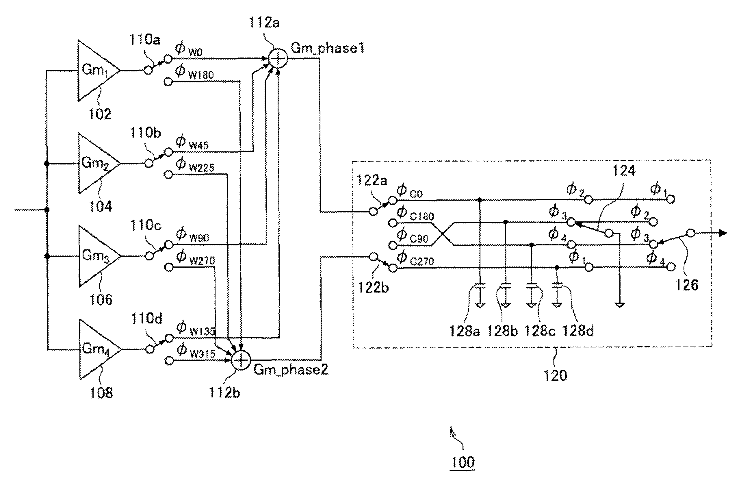
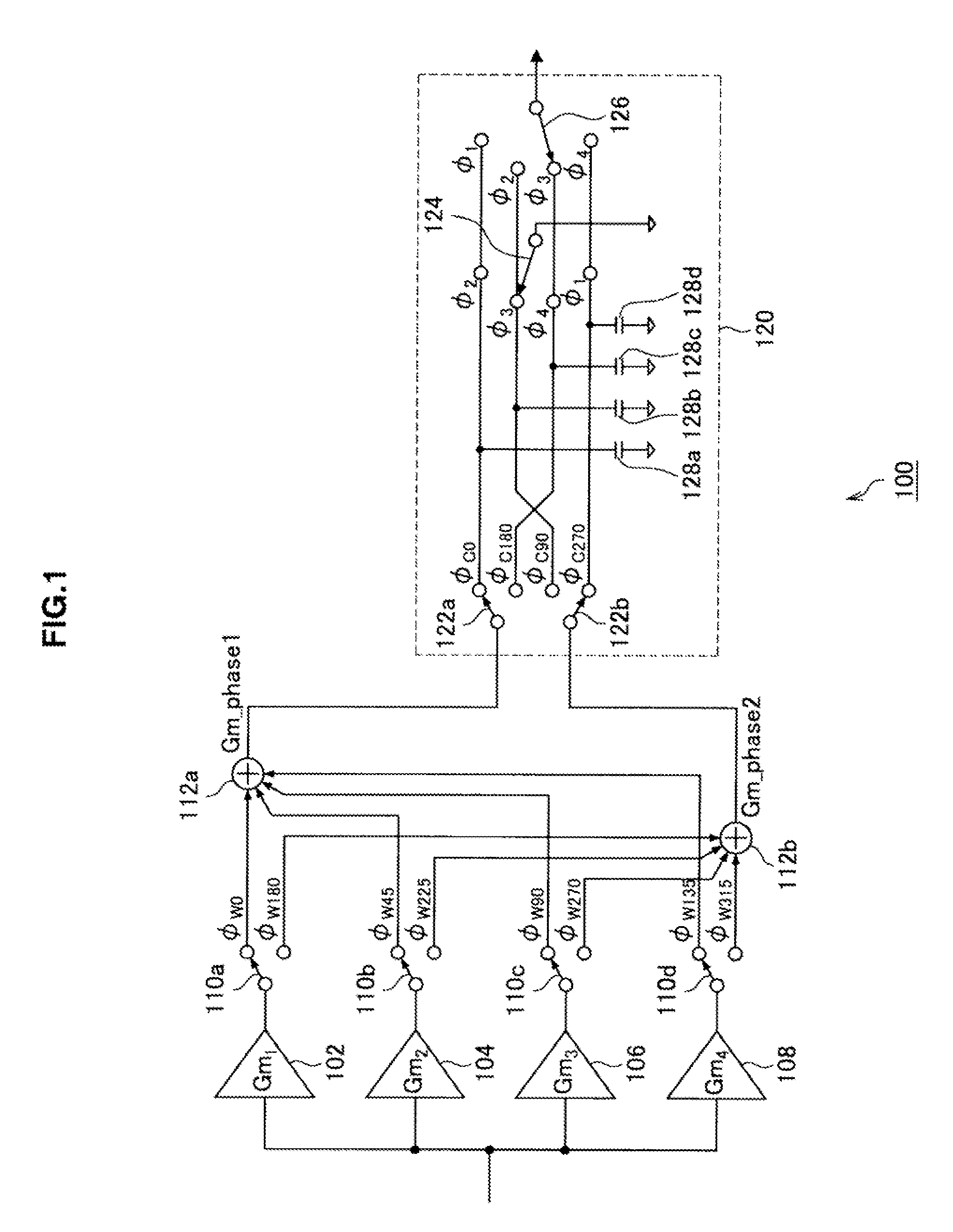
[0050]FIG. 1 shows the charge domain filter circuit achieved in the first embodiment of the present invention. As shown in FIG. 1, the charge domain filter circuit 100 in the first embodiment of the present invention includes transconductors 102, 104, 106 and 108, switches 110a, 110b, 110c and 110d, adders 112a and 112b and a SINC filter circuit 120.
[0051]The SINC filter circuit 120 includes first switches 122a and 122b, a second switch 124, a third switch 126 and capacitors 128a, 128b, 128c and 128d.
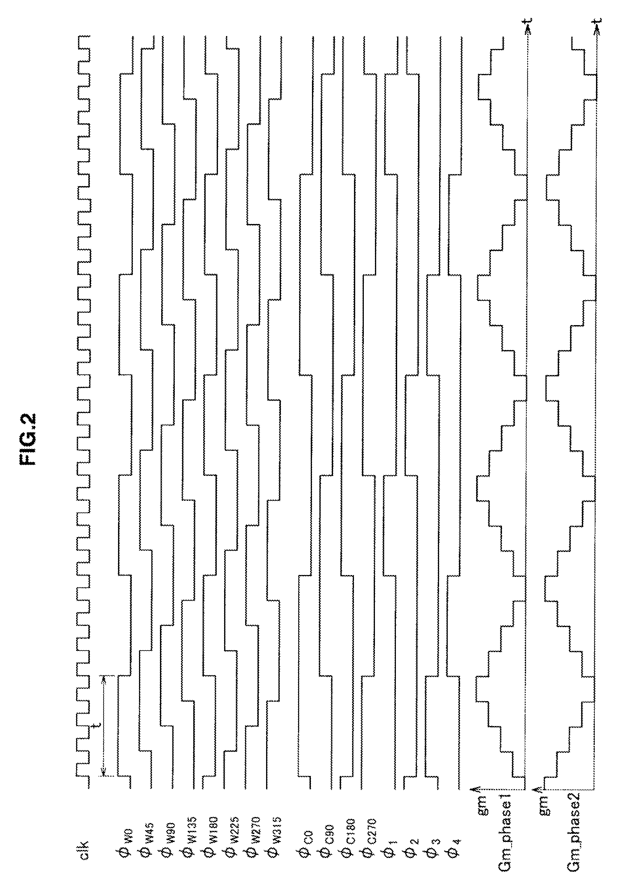
[0052]The transconductors 102, 104, 106 and 108 each output a current in proportion to the voltage of an input signal. While four transconductors are used to constitute the charge domain filter circuit in the embodiment, the number of transconductors in a charge domain filter circuit embodying the present invention is not limited to four. In addition, the transconductors...
second embodiment
[0103]An explanation is given above in reference to the first embodiment of the present invention on a charge domain filter circuit, the frequency characteristics of which can be adjusted freely by controlling the timing with which the currents output from the transconductors are added up. Now, in reference to the second embodiment of the present invention, a charge domain filter circuit, the frequency characteristics of which can be adjusted freely by controlling the timing with which the electrical charges output from SINC filter circuits are added up, is described.
[0104]FIG. 7 illustrates the charge domain filter circuit achieved in the second embodiment of the present invention. The following is an explanation of the charge domain filter circuit achieved in the second embodiment of the present invention, given in reference to FIG. 7.
[0105]As shown in FIG. 7, a charge domain filter circuit 200 in the second embodiment of the present invention includes transconductors 202, 204, 20...
application example 1
[0147]FIGS. 9A and 9B illustrate an example of impulse response. When the pulse width of the clocks used to charge the capacitors includes three clocks and the charge domain filter circuit includes five transconductors, with three transconductors among them assuming a transconductance twice that of the remaining two, as shown in FIG. 9A, the impulse response shown in FIG. 9B is obtained. The impulse response shown in FIG. 9B is identical to that shown in FIG. 5B. Accordingly, assuming that the sampling cycle t is equal to 1 ns, the frequency characteristics achieved under these circumstances, too, are as indicated by the graph in FIG. 6.
PUM
 Abstract
Description
Claims
Application Information
 - R&D
- Intellectual Property
- Life Sciences
- Materials
- Tech Scout
- Unparalleled Data Quality
- Higher Quality Content
- 60% Fewer Hallucinations
Browse by: Latest US Patents, China's latest patents, Technical Efficacy Thesaurus, Application Domain, Technology Topic, Popular Technical Reports.
© 2025 PatSnap. All rights reserved.Legal|Privacy policy|Modern Slavery Act Transparency Statement|Sitemap|About US| Contact US: help@patsnap.com


