Turbine blade tip with mini-serpentine cooling circuit

a cooling circuit and turbine blade technology, applied in the field of fluid reaction surfaces, can solve the problems of excessive wear or damage of the tip and shroud, reduce the efficiency of the engine, and leakage of hot gas, and achieve the effect of increasing the internal heat transfer cooling and increasing the film cooling effect of the blad

Inactive Publication Date: 2009-05-26
FLORIDA TURBINE TECH
View PDF11 Cites 56 Cited by
  • Summary
  • Abstract
  • Description
  • Claims
  • Application Information

AI Technical Summary

Benefits of technology

[0012]The present invention is a turbine blade having a tip squealer in which a plurality of mini-serpentine cooling channels are arranged parallel with the tip cap to provide cooling for the tip cap of the blade. The mini-serpentine cooling channels can be either three-pass, four-pass or five-pass serpentine channel. An inlet to the serpentine channel communicates with the serpentine cooling channel within the blade internal cooling circuit. An exit to the serpentine cooling channel discharges cooling air onto the pressure side of the blade tip to provide film cooling. The mini-serpentine channels can be arranged parallel or transverse to the blade cord-wise length. Trip strips are used in the serpentine flow channels to increase the internal heat transfer cooling. Thin film diffusion slots at the hole exit increase the film cooling effect of the blade.

Problems solved by technology

Leakage across this seal reduces the engine efficiency.
Also, the leakage is hot gas flowing between the tip and the shroud.
This hot gas flow on the tip will cause heating of the blade tip resulting in excessive wear or damage to the tip and shroud.
Rubbing of the tip against the shroud is also a problem because of thermal expansion of the blade from the heat load and from the centrifugal force developed in the blade from the rotation thereof.
Leakage in to the squealer tip cavity of the hot gas flow will cause the balder tip region to overheat.

Method used


Image

  • Turbine blade tip with mini-serpentine cooling circuit
  • Turbine blade tip with mini-serpentine cooling circuit
  • Turbine blade tip with mini-serpentine cooling circuit

Examples


Embodiment Construction

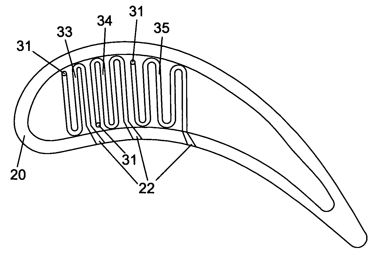
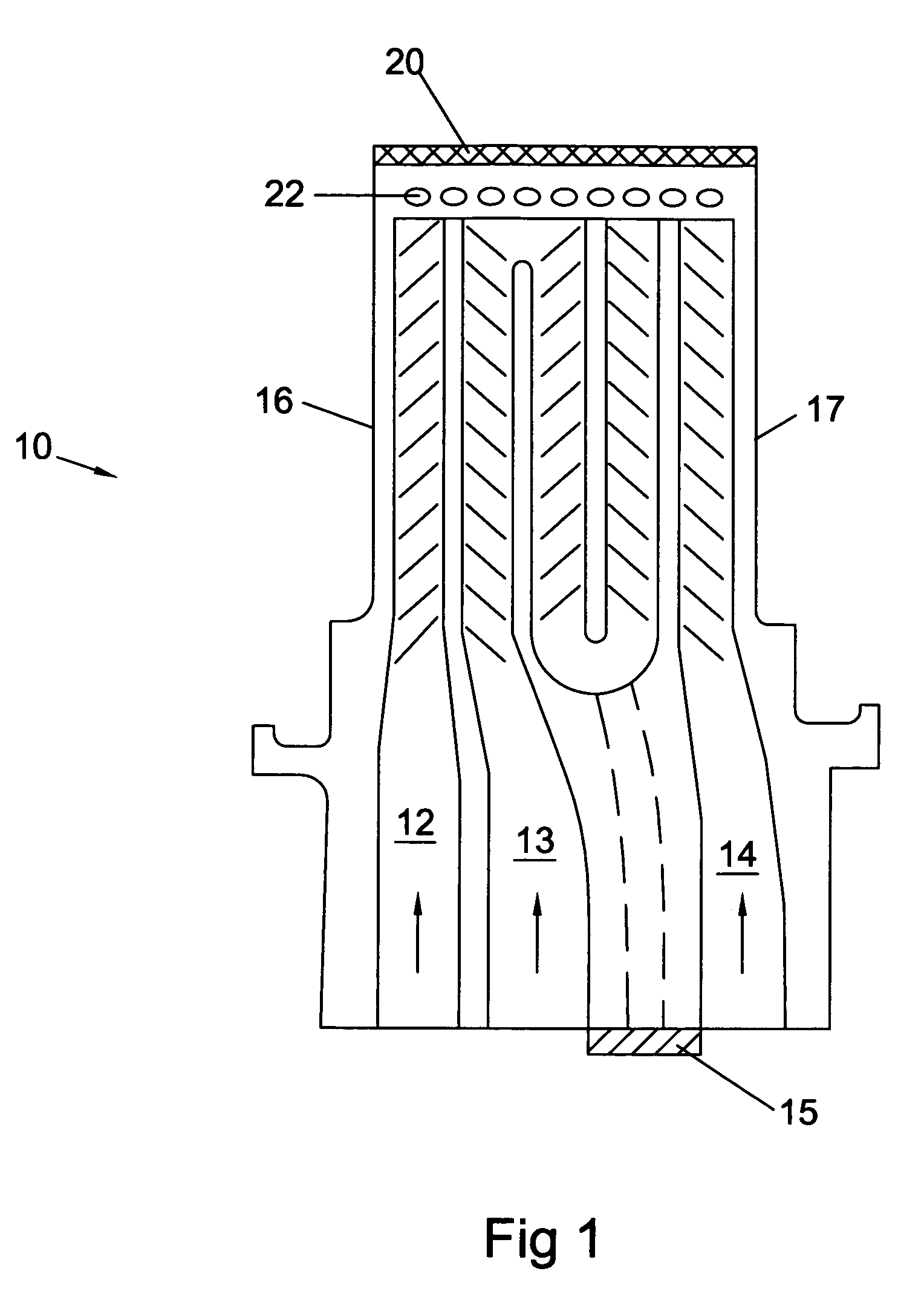
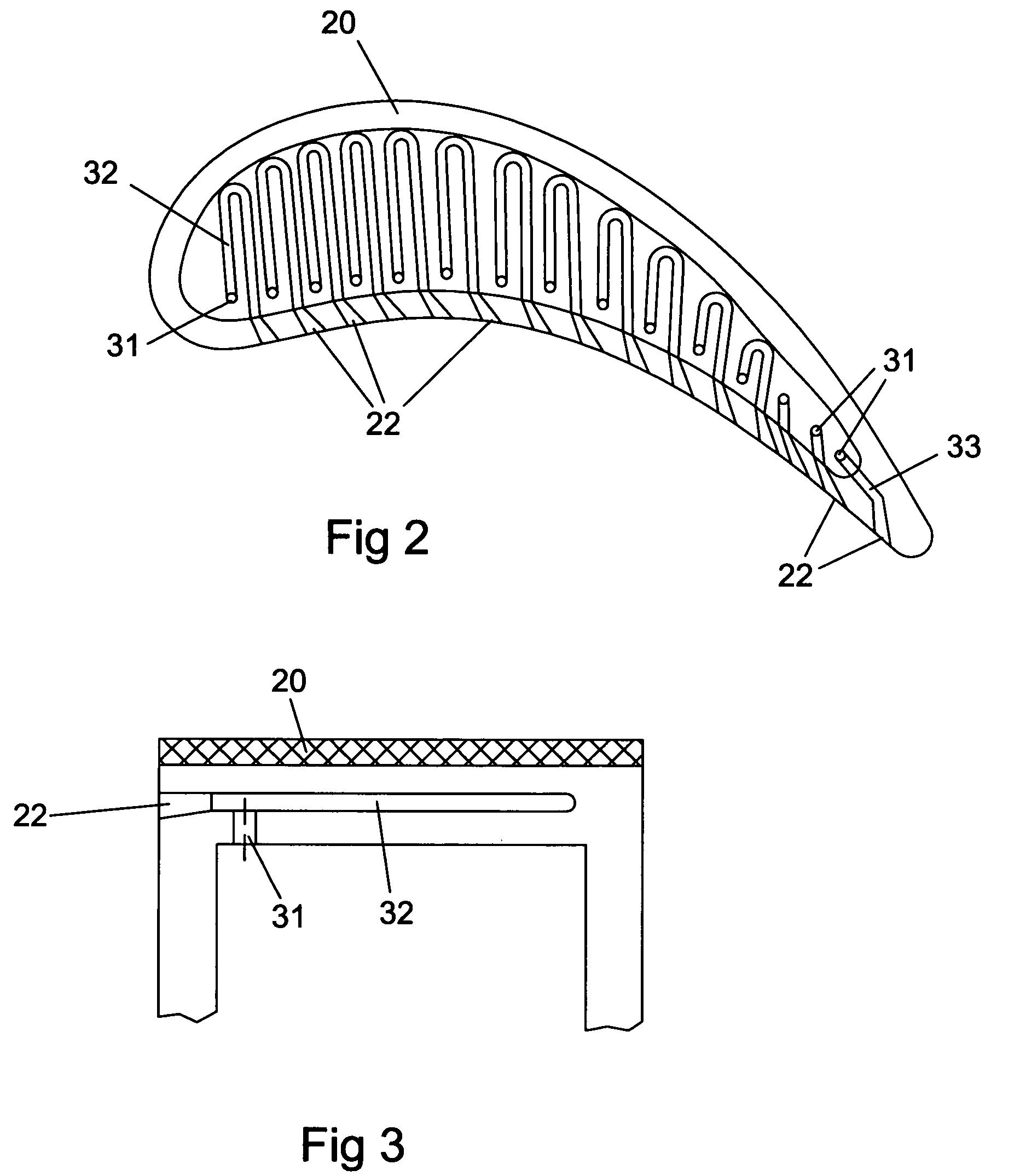
[0025]The present invention is a turbine blade used in a gas turbine engine, the blade having an internal cooling circuit for cooling the blade and a tip region. The tip of the blade is cooled with air supplied from the internal serpentine cooling passages and through a plurality of mini-serpentine cooling channels arranged along the surface that forms the blade top. The blade top also forms the floor for the squealer tip. FIG. 1 shows a cross section view of the blade 10 of the present invention, the blade including a leading edge 16 and a trailing edge 17, and three cooling supply channels. A leading edge cooling supply channel 12 supplies cooling air to a leading edge cooling structure such as a showerhead configuration. A mid-chord cooling supply channel 13 forms a serpentine passage through the interior of the blade. A trailing edge cooling supply channel 14 supplies cooling air to the trailing edge region through a plurality of cooling passages and discharge holes. An abrasive...


PUM


Abstract

A turbine blade having a cooling supply passage formed within the blade, and a blade tip with a squealer tip formed thereon. The blade tip includes a blade top or cap, and includes a plurality of mini-serpentine cooling channels formed within the tip. The mini-serpentine channels can be 2-pass, 3-pass, 4-pass, or 5-pass serpentine channels, and each includes an inlet hole connected to the internal cooling supply passage to pass cooling air through the channels. Each channel includes an exit hole with a diffuser that opens onto the pressure side of the blade to provide film cooling. The mini-serpentine cooling channels can be arranged to flow substantially from blade side to side or from blade edge to edge.

Description

CROSS-REFERENCE TO RELATED APPLICATIONS[0001]This application relates to co-pending and recently filed regular patent application Ser. No. 11 / 503,549 entitled TURBINE AIRFOIL WITH MINI-SERPENTINE COOLING PASSAGES.BACKGROUND OF THE INVENTION[0002]1. Field of the Invention[0003]The present invention relates generally to fluid reaction surfaces, and more specifically to a gas turbine blade with tip cooling.[0004]2. Description of the Related Art including information disclosed under 37 CFR 1.97 and[0005]A gas turbine engine includes a turbine section with a plurality of rotor blade stages. A compressor supplies compressed air to a combustor to produce a hot gas flow through the turbine resulting in the generation of mechanical power. The rotating blades of the turbine form a seal between the blade tips and the outer shroud wall of the turbine. Thus, a seal is formed between two relatively rotating members of the turbine.[0006]Leakage across this seal reduces the engine efficiency. Also...

Claims


Application Information

Patent Timeline
Patent Type & Authority Patents(United States)
IPC IPC(8): F01D5/08F01D5/18
CPCF01D5/187F01D11/122F05D2260/202F05D2260/2214F05D2240/307F05D2250/185F05D2260/204
Inventor LIANG, GEORGE
Owner FLORIDA TURBINE TECH
Why Eureka
Try Eureka