Optical recording medium and process for producing the same

a technology of optical recording medium and optical recording medium, which is applied in the field of optical recording medium, can solve the problems of not being able to obtain good signal quality, not being able to carry out tracking control, and not being able to receive adverse effects

Active Publication Date: 2009-05-26
PANASONIC CORP
View PDF26 Cites 4 Cited by
  • Summary
  • Abstract
  • Description
  • Claims
  • Application Information

AI Technical Summary

Benefits of technology

[0054]In the optical recording medium of the present invention, the pit depth d is set in a range, (λ / (5n)≦d≦λ / (3n)), so as to obtain sufficient playback signal, with the depth λ / (4n) that fails to provide a sufficient size of amplitude of a push-pull tracking error signal being excluded. With this arrangement, a sufficient playback signal can be obtained from a signal face made of pits on the reflective layer, thereby making it possible to provide tracking control by using a push-pull tracking control system.

Problems solved by technology

However, the size of this TEpp signal amplitude fails to provide sufficient gain used for tracking control, with the result being that the tracking control is not carried out by receiving adverse effects due to influences of shape changes caused by vibration and deviations in disk manufacturing processes.
Furthermore, the degree of modulation that represents the size of amplitude of the playback signal RF was 0.40 and the playback signal jitter that represents signal quality was 6.7%, thus, in comparison with the reproducing operation of the first signal face 206, although the push-pull tracking error signal TEpp is prepared as virtually the same signal, the degree of modulation that represents the size of amplitude of the playback signal RF and the playback signal jitter that represents signal quality show that it is not possible to obtain good signal quality due to influences from insufficient transferring of the signal face.
Based upon these facts, it is not possible to carry out tracking control and it is also not possible to obtain a sufficient jitter value that represents playback signal quality, unless a phase-difference tracking system having large power consumption is adopted.
However, the problem with this phase difference tracking system is that high power consumption is required.
However, in the case of the push-pull tracking control system being adopted, due to the fact that the optical depth of pits on the signal face is set to just λ / (4n), it is not possible to obtain a sufficient amplitude in the tracking error signal.
Moreover, upon transferring and forming signal pits having the optical depth of λ / (4n) by using photo-curing resin, due to miniaturized pits used for preparing high-density signals, it is not possible to carry out an even transferring process over the entire signal face, resulting in a failure in providing sufficient playback signal quality for reproduction.

Method used


Image

  • Optical recording medium and process for producing the same
  • Optical recording medium and process for producing the same
  • Optical recording medium and process for producing the same

Examples


embodiment 1

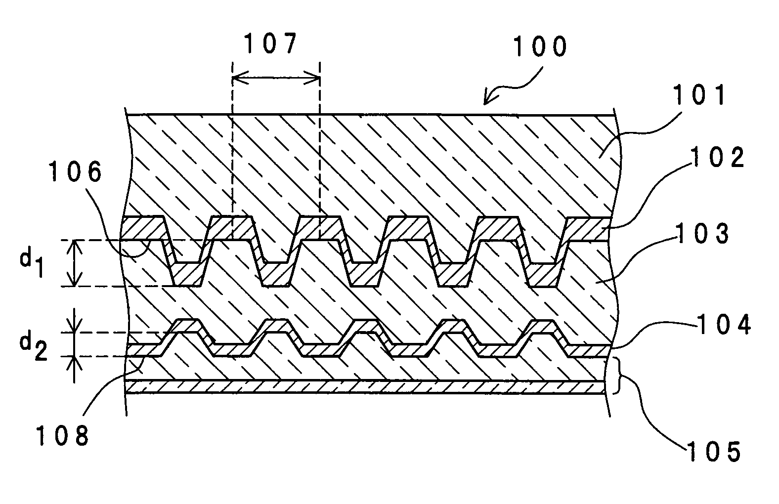
[0069]The following description will discuss an optical recording medium and manufacturing method thereof in accordance with first embodiment of the present invention. With respect to the signal reproducing system of this optical recording medium 100, a reproducing head having a semiconductor laser wavelength of 400 nm with NA of 0.85 is used. Moreover, the following description discusses a case in which: the track pitch TP of signals formed on the first signal layer and the second signal layer of the optical recording medium is 0.32 μm and the pit length of a 2T signal that forms the shortest pit upon adopting a 1-7 modulation system as the signal modulation system is 0.149 μm.

[0070]FIG. 1 is a cross-sectional view that shows an optical disk in accordance with embodiment 1 of the present invention. This optical disk 100 has a structure in which a first substrate 101, a first reflective layer 102, a second substrate 103, a second reflective layer 104 and a cover layer 105 are succes...

embodiment 2

[0117]FIG. 10 is a cross-sectional view that shows a cross-sectional structure of an optical disk 100b in accordance with embodiment 2. In comparison with the optical disk in accordance with embodiment 1, this optical recording medium 100b is different in that only one signal face for recording signals is prepared. This optical disk 100b is provided with a substrate 101 that has convex-shaped pits on one of the faces, a reflective layer 102 that is formed on the convex-shaped pits of the first substrate 101 in a manner so as to reflect the recesses and lands, and a cover layer 105 that is formed on the reflective layer 102. A signal face 106 made of convex-shaped pits is formed on the reflective layer 102.

[0118]In the optical disk 100b, with respect to a pit depth d that corresponds to a difference between the recesses and lands of the reflective layer 102, the wavelength λ of signal-reproducing laser light and the refractive index n of the cover layer 105, the following relational ...

embodiment 3

[0119]FIG. 11 is a cross-sectional view that shows a cross-sectional structure of an optical disk 100c in accordance with third embodiment. In comparison with the optical disk in accordance with embodiment 1, this optical disk 100c is different in that three layers of signal faces for recording signals are prepared. This optical disk 100c is provided with a first substrate 101, a first reflective layer 102, a second substrate 103, a second reflective layer 104, a third substrate 111, a third reflective layer 112 and a cover layer 105 that are successively laminated in this order. The first substrate 101 has convex-shaped first pits on one of the faces. The first reflective layer 102 is formed on the concave-shaped first pits of the first substrate 101 in a manner so as to reflect the recesses and lands. This first reflective layer 102 has a first signal face 106 made of concave-shaped pits. The second substrate 103, which is formed on the first reflective layer 102, has second conve...


PUM

PropertyMeasurementUnit
thicknessaaaaaaaaaa
total thicknessaaaaaaaaaa
depthaaaaaaaaaa

Abstract

An optical recording medium is provided with: a first substrate having first pits on one face thereof; a first reflective layer that is formed on the face bearing the first pits of the first substrate in a manner so as to reflect lands and recesses of the first pits; a second substrate that is formed on the first reflective layer, with second pits being formed on a face on the side opposite to the first reflective layer; a second reflective layer that is formed on the face bearing the second pits of the second substrate in a manner so as to reflect lands and recesses of the second pits; and a cover layer formed on the second reflective layer. In this structure, the first pit depth d1 that is a difference between lands and recesses of the first reflective layer, the wavelength λ of signal-reproducing laser light and the refractive index n1 of the second substrate satisfy the following relational expressions: λ / (5n1)≦d1≦λ / (3n1) and d1≠λ / (4n1). Moreover, the second pit depth d2, which is a difference between lands and recesses of the second reflective layer, the wavelength λ of signal-reproducing laser light and the refractive index n2 of the cover layer satisfy the following relational expressions: λ / (5n2)≦d2≦λ / (3n2) and d2≠λ / (4n2).

Description

FIELD OF THE INVENTION[0001]This invention relates to an optical recording medium of a high-density laminated-layer type for use in a reproducing and manufacturing method in which such an optical recording medium is manufactured by using a stacking method or a laminating method.BACKGROUND ART[0002]In recent years, along with an expanded amount of information required by an information apparatus, an image audio apparatus and the like, public attention has been focused on an optical disk as a recording medium, because of its ease in data access, capability of storing a large amount of data, and compactness, wherein an attempt has been made to achieve high-density recorded information on such a recording medium. For example, with respect to a method for achieving a high-density optical disk, an optical recording medium has been proposed in which: by using a reproducing head with a numeric aperture (NA) of 0.85 as a condensing lens for converging laser light, with a laser-beam wavelengt...

Claims


Application Information

Patent Timeline
Patent Type & Authority Patents(United States)
IPC IPC(8): G11B7/24G11B7/007G11B7/013G11B7/24038G11B7/24079G11B7/24085
CPCG11B7/24038G11B7/24079G11B7/24085
Inventor TOMIYAMA, MORIOABE, SHINYAKAWAGUCHI, YUUKOOHNO, EIJI
Owner PANASONIC CORP
Why Eureka
Try Eureka