Dual recycling/transfer furnace flow management valve for low melting temperature metals

a technology of flow management valve and low melting temperature metal, which is applied in the direction of liquid transfer device, liquid/fluent solid measurement, packaging, etc., can solve the problems of furnace, molten material, furnace energy cost, etc., and achieve the effect of increasing the flow rate of the pump, facilitating gas injection without increasing the velocity of the pump, and maximum efficiency

Inactive Publication Date: 2009-06-09
MORANDO JORGE A
View PDF8 Cites 76 Cited by
  • Summary
  • Abstract
  • Description
  • Claims
  • Application Information

AI Technical Summary

Benefits of technology

[0014]It is an advantage of the present invention to provide a flow control valve that eliminates the need for two different pumps for re-circulating and transferring molten metal from a furnace. The flow control valve allows a single pump operating at its maximum efficiency (e.g., pumping 2000-3000 gallons per minute) to re-circulate a bath of molten metal within a furnace and to transfer the molten metal out of the furnace at a desired rate (e.g., 300 gallons per minute) by redirecting some of the flow from re-circulating into a transfer portion of the valve.
[0015]It is another advantage of the present invention that the valve allows adjustment of the transfer and recirculation flows to fit different needs and pump speeds.
[0016]It is still another advantage that present invention eliminates conventional transfer tube risers and elbows, whose restrictive size and ninety degree bends tend to leak and break due to the high velocity of the metal flow and the vibration in the pump.
[0017]It is yet another advantage of the present invention that the valve is placed immediately downstream from the pump outlet, effective to move the placement of any gas injection tubes further away from the pump. By injecting at the valve outlet rather than adjacent to the pump outlet, the valve receives the brunt of the vibration from the gas expansion and dross formation, rather than the pump. Further, the valve can be partially closed or “choked” to increase the flow rate from the pump to facilitate gas injection without increasing the velocity of the pump, allowing the pump to remain running at its maximum efficiency.
[0018]It is still yet another advantage of the present invention that the valve can be placed in a continuous casting position, which, in conjunction with the pump velocity, matches the transferred metal rate (per hour) to the furnace melting rate, eliminating the need to empty the furnace in batches.
[0019]These and other objects, features and advantages of the present invention will become apparent from the following description when viewed in accordance with the accompanying drawings and appended claims.

Problems solved by technology

The energy cost to run a molten metal furnace in batches (where the furnace is loaded with solid material, the solid material is melted, and then the molten material is transferred out of the furnace) is expensive and time-consuming.

Method used


Image

  • Dual recycling/transfer furnace flow management valve for low melting temperature metals
  • Dual recycling/transfer furnace flow management valve for low melting temperature metals
  • Dual recycling/transfer furnace flow management valve for low melting temperature metals

Examples


Embodiment Construction

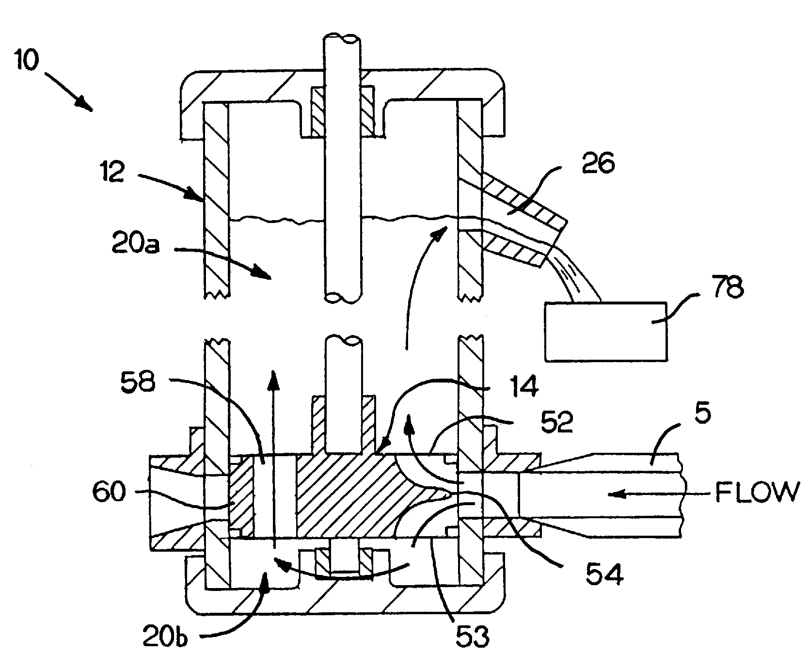
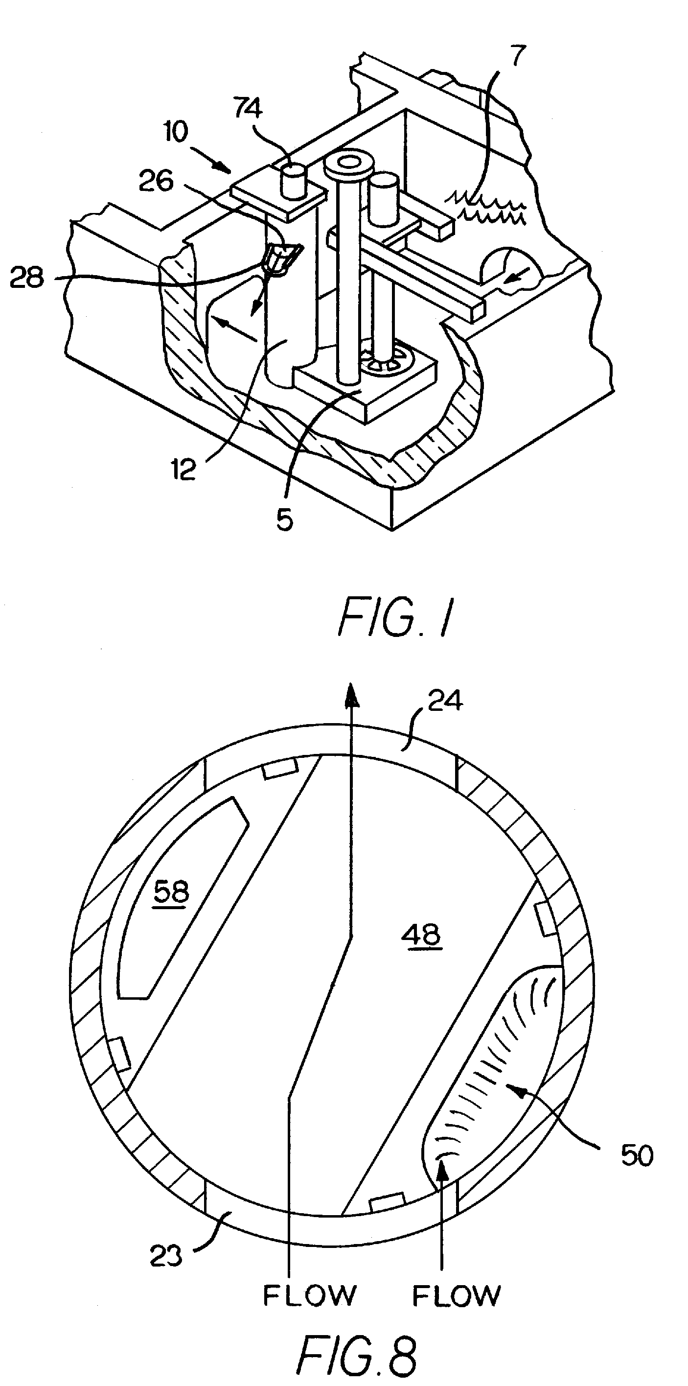
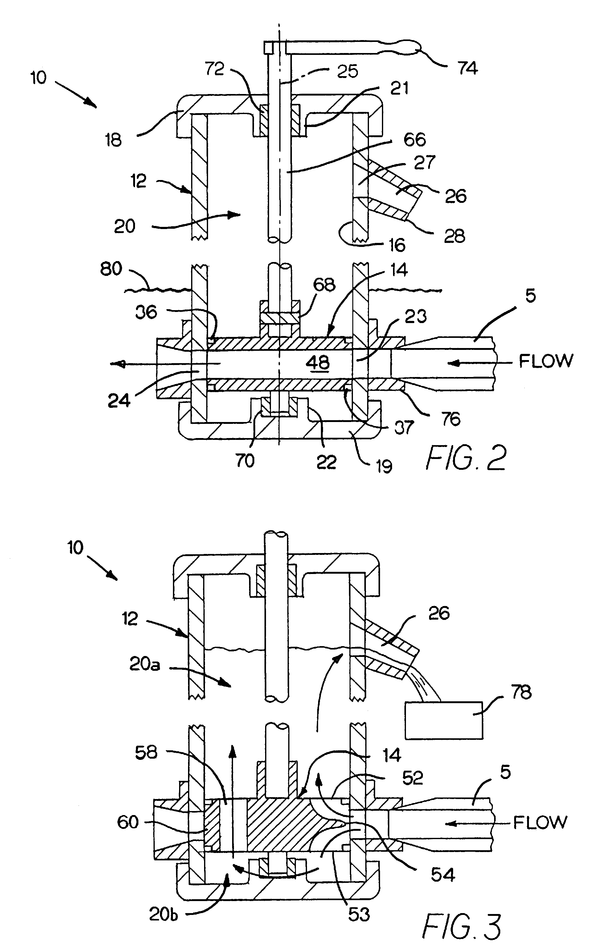
[0030]A conventional furnace is generally shaped as a fluid retaining enclosure. This enclosure includes a heating area or hearth, a pump well that contains a molten metal pump 5 and a charge well. A bath 7 of molten metal is contained within the furnace. A series of arches fluidly connect the hearth, pump well and charge well allowing the molten metal to flow through the furnace. During normal operation, the bath 7 is heated in the hearth, pulled into the pump well by pump 5 and accelerated out from the pump and into the charge well to circulate the molten metal through the furnace.

[0031]Pump 5 is typically a centrifugal impeller pump adapted to be immersed in molten metal. Pump 5 rotates an impeller to draw in and expel the molten metal forming bath 7. One example of such a pump is the type disclosed in my U.S. Pat. No. 7,326,028 entitled HIGH FLOW / DUAL INDUCER / HIGH EFFICIENCY IMPELER FOR LIQUID APPLICATIONS INCLUDING MOLTEN METAL, incorporated herein by reference. It should be ap...


PUM

PropertyMeasurementUnit
latent heat of fusionaaaaaaaaaa
temperatureaaaaaaaaaa
energyaaaaaaaaaa

Abstract

A furnace flow control valve for use within a bath of molten metal. The flow control valve includes a vertically-disposed elongated tubular stator, which is configured to receive flow from a molten metal pump. The valve has a rotor which is sealing rotatable within the stator between: a full re-circulation position, where flow from the pump passes un-hindered through the valve; a full transfer position, where flow from the pump is redirected into the vertically disposed stator and out of the valve; and a partial re-circulation/partial transfer position where flow from the pump both passes through the valve and is transferred up and out of valve through the stator.

Description

FIELD OF THE INVENTION[0001]The present invention relates to the transfer of molten metal and, more particularly, to the construction of a recycling furnace flow control apparatus including a molten metal immersible valve that re-directs the flow from a dual circulation / transfer pump from circulating a molten metal bath to transferring the molten metal out of the furnace.BACKGROUND OF THE INVENTION[0002]A typical molten metal facility includes a furnace with one or more pumps for moving molten metal. During the processing of molten metals, such as aluminum, the molten metal is normally continuously circulated through the furnace by a centrifugal impeller pump, i.e., a circulation pump, to equalize the temperature of the molten bath. A typical furnace includes a pump well that is located between the heating chamber or hearth and the charge well (where raw material is inserted into the furnace). These three main sections of a typical furnace are fluidly interconnected with the circula...

Claims


Application Information

Patent Timeline
Patent Type & Authority Patents(United States)
IPC IPC(8): F16K11/085B22D37/00
CPCB22D37/00Y10T137/86871
Inventor MORANDO, JORGE A.
Owner MORANDO JORGE A
Why Eureka
Try Eureka