
System for selectively blocking electromagnetic energy

a selective blocking and electromagnetic technology, applied in the direction of instruments, waveguide devices, polarising elements, etc., can solve the problems of avoiding the use of dielectrics, prone to breakdown and/or overheating, etc., to facilitate the new design of the system, low loss, and high thermal conductivity

Active Publication Date: 2009-06-09
RAYTHEON CO
View PDF9 Cites 3 Cited by
  • Summary
  • Abstract
  • Description
  • Claims
  • Application Information

AI Technical Summary

Benefits of technology

The present invention is a system for selectively blocking electromagnetic energy. It is designed to protect high-power millimeter wave components from reflected energy. The system includes a first mechanism for passing a beam with a first property and rejecting a beam with a second property. The second mechanism selectively alters the beam so that it exhibits the second property upon reflection. The key components of the system are constructed from thick perforated metallic plates, which have low losses and high thermal conductivity, minimizing energy loss and providing a low thermal resistance path for the removal of absorbed energy. The system can handle high power levels and is suitable for use in high-power millimeter wave applications.

Problems solved by technology

The use of perforated metallic plates to implement the beamsplitter and quarter-wave plate obviates the use of dielectrics, which are susceptible to breakdown and / or overheating.

Method used


Image

  • System for selectively blocking electromagnetic energy
  • System for selectively blocking electromagnetic energy
  • System for selectively blocking electromagnetic energy

Examples


Embodiment Construction

[0019]While the present invention is described herein with reference to illustrative embodiments for particular applications, it should be understood that the invention is not limited thereto. Those having ordinary skill in the art and access to the teachings provided herein will recognize additional modifications, applications, and embodiments within the scope thereof and additional fields in which the present invention would be of significant utility.

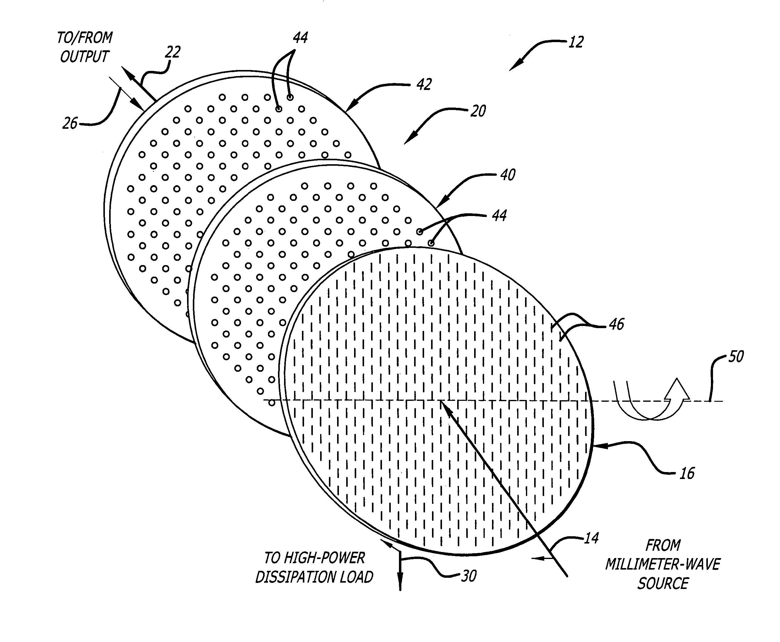
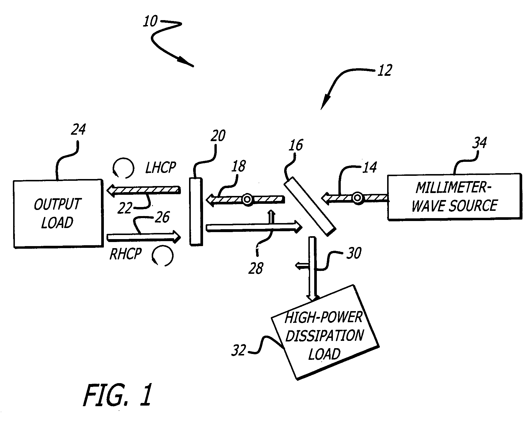
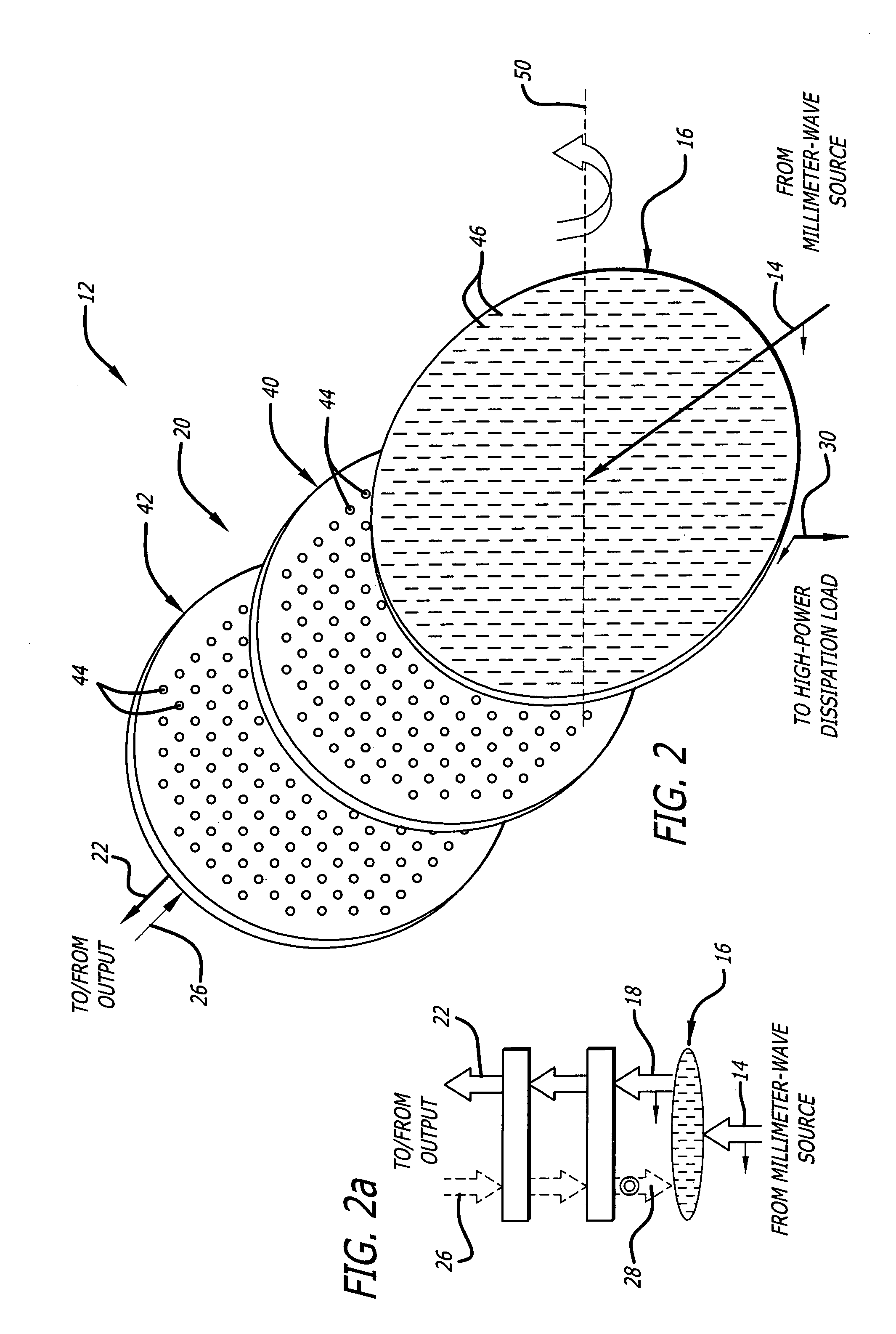
[0020]FIG. 1 is a diagram illustrating a quasioptical system 10 having a millimeter-wave isolator 12 with a perforated metallic beamsplitter 16 and a perforated metallic quarter-wave plate 20 constructed in accordance with the teachings of the present invention. For clarity, various features, such as microwave amplifiers, and power supplies, have been omitted from the figures. However, those skilled in the art with access to the present teachings will know which features to implement and how to implement them to meet the needs of a gi...


PUM

PropertyMeasurementUnit
frequenciesaaaaaaaaaa
widthaaaaaaaaaa
widthaaaaaaaaaa

Abstract

A system for selectively blocking electromagnetic energy. The system includes a first mechanism for employing a perforated component to pass a beam characterized by a first property and reject a beam characterized by a second property. A second mechanism selectively alters a beam passed by the first mechanism so that upon reflection, the beam exhibits the second property. In a specific embodiment, the first property corresponds to a first polarization, and the second property corresponds to a second polarization. In the specific embodiment, the perforated component includes a beamsplitter having a first perforated metallic plate. The second mechanism includes a quarter-wave plate having a second perforated metallic plate.

Description

BACKGROUND OF THE INVENTION[0001]1. Field of Invention[0002]This invention relates to systems for directing or controlling energy. Specifically, the present invention relates to isolators for selectively blocking, redirecting, or absorbing reflected energy, such as microwave energy.[0003]2. Description of the Related Art[0004]Isolators are employed in various demanding applications including communications, space-based remote sensing systems, and military avionics. Such applications demand efficient and cost-effective isolators that can accommodate large amounts of reflected power without damage.[0005]In relatively low-frequency applications involving radio-frequency waves, wave reflections are often attenuated via ferrite-based microstrip or waveguide circulators and isolators. Microstrip implementations of these devices have relatively low power-handling capability, while waveguide-based devices are often unacceptably lossy at multi-kilowatt power levels and frequencies beyond 10 ...

Claims


Application Information

Patent Timeline
Patent Type & Authority Patents(United States)
IPC IPC(8): G02B27/14G01N21/00G02B27/28H01P1/08H01Q3/26H01Q15/00H01Q15/24
CPCH01Q15/244H01Q15/0026
Inventor CROUCH, DAVID D.
Owner RAYTHEON CO
Learn More