UV assisted thermal processing

a technology of thermal processing and uv radiation source, which is applied in the direction of measuring devices, instruments, electric discharge tubes, etc., can solve problems such as promoting unwanted diffusion inside other structures

Inactive Publication Date: 2009-06-16
APPLIED MATERIALS INC
View PDF25 Cites 334 Cited by
  • Summary
  • Abstract
  • Description
  • Claims
  • Application Information

AI Technical Summary

Problems solved by technology

The higher temperature required for breaking oxygen or other species increases thermal exposure, promote unwanted diffusion inside other structures.

Method used


Image

  • UV assisted thermal processing
  • UV assisted thermal processing
  • UV assisted thermal processing

Examples


Embodiment Construction

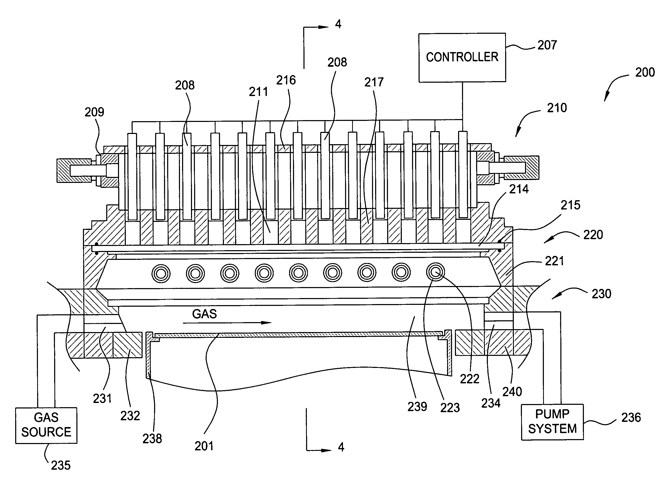
[0020]The present invention provides methods and apparatus for performing thermal processing of a semiconductor substrate. Thermal processing chambers of the present invention comprise two different radiation energy sources, such as an infrared radiation source and a UV radiation source. The UV radiation source and the infrared radiation source may be used alone or in combination to supply heat, activate electronic, or create active species inside the thermal processing chamber. A plurality of processes, such as rapid thermal processing, annealing, and oxidation, may be performed in the thermal processing chamber with improved results. The combined use of infrared and UV radiation enables surface selective reactions which is not possible by using either radiation alone.

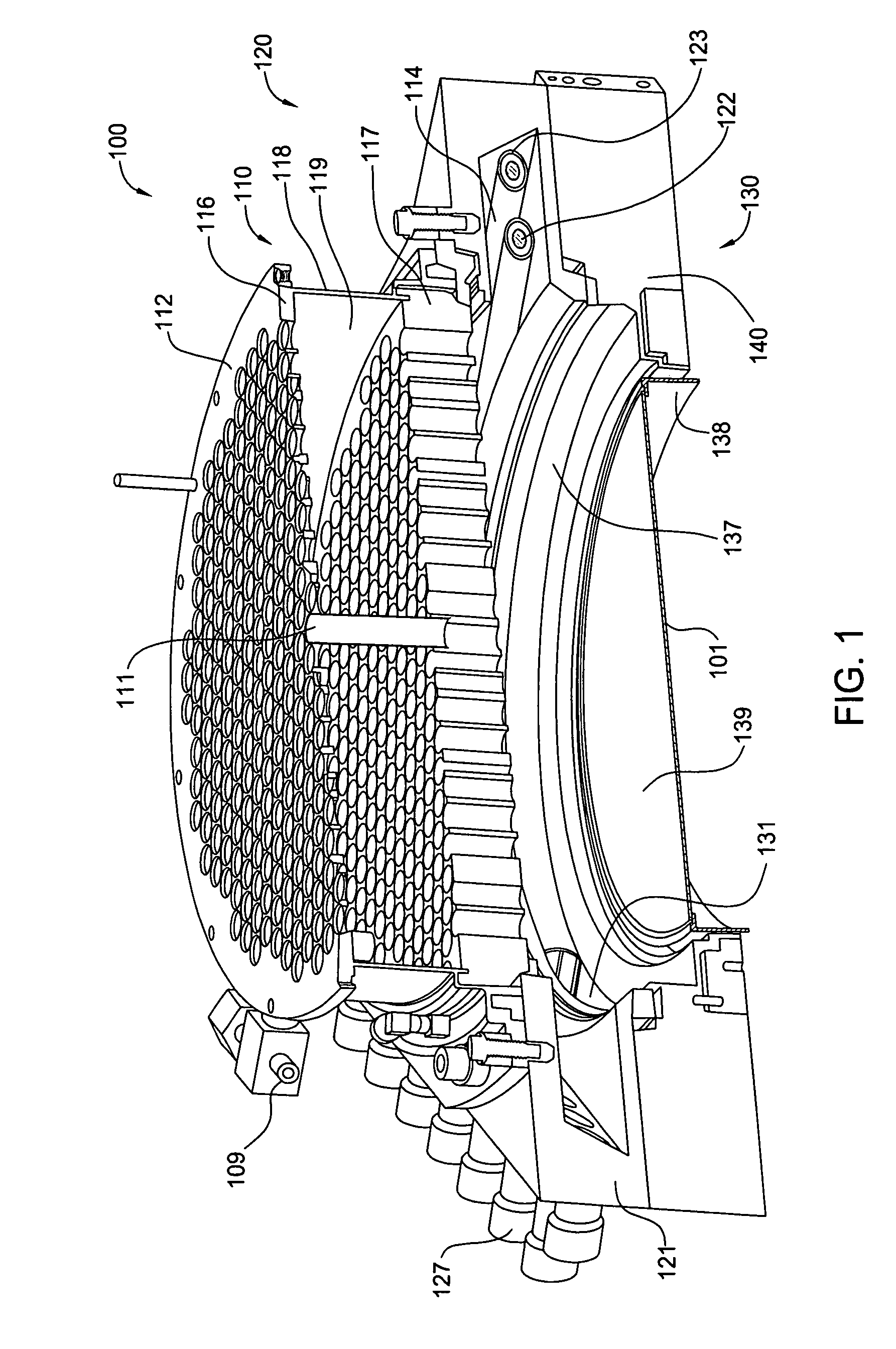
[0021]FIG. 1 illustrates a sectional perspective view of a thermal processing chamber 100 in accordance with one embodiment of the present invention. The thermal processing chamber 100 generally comprises a lamp assem...


PUM


Abstract

The present invention provides methods and apparatus for performing thermal processes to a semiconductor substrate. Thermal processing chambers of the present invention comprise two different energy sources, such as an infrared radiation source and a UV radiation source. The UV radiation source and the infrared radiation source may be used alone or in combination to supply heat, activate electronic, or create active species inside the thermal processing chamber.

Description

BACKGROUND OF THE INVENTION[0001]1. Field of the Invention[0002]The present invention relates generally to a semiconductor processing tool and, more specifically, to a thermal processing tool with a UV radiation source.[0003]2. Description of the Related Art[0004]Rapid Thermal Processing, commonly referred to as ‘RTP’, subjects a substrate to a very brief, intense burst of heat that can go from room temperature to about 1000° C. in seconds. RTP technology is used to change the characteristics of a deposited film or crystal lattice. RTP generally includes processes such as annealing, silicidation and oxidation of a substrate surface.[0005]Generally, an RTP chamber includes a radiant heat source or lamp, a chamber body, and a substrate support ring. The lamp is typically mounted on a top surface of the chamber body so that the energy generated by the lamp radiates upon the substrate supported by the substrate support ring with in the chamber body. A quartz window is typically disposed...

Claims


Application Information

Patent Timeline
Patent Type & Authority Patents(United States)
IPC IPC(8): H01L21/31
CPCH01L21/67115H01L21/324
Inventor RANISH, JOSEPH MICHAELYOKOTA, YOSHITAKA
Owner APPLIED MATERIALS INC
Why Eureka
Try Eureka