Real-time geo-registration of imagery using COTS graphics processors

a graphics processor and imagery technology, applied in the field of geo-registration methods, can solve the problems of difficult real-time visualization of live data, high computational cost of image processing, and inability to accurately represent the image, and achieve the effect of less expensive and higher resolution images

Inactive Publication Date: 2009-06-30
LAWRENCE LIVERMORE NAT SECURITY LLC
View PDF8 Cites 13 Cited by
  • Summary
  • Abstract
  • Description
  • Claims
  • Application Information

AI Technical Summary

Benefits of technology

[0011]The present invention is directed to a geo-registration method for performing transformations of high-resolution digital imagery that operates in real time, is faster and typically produces higher resolution images than software only or custom hardware / dedicated pixel processor techniques, and is less expensive than such existing techniques by using commercial off-the-shelf (COTS) image processing hardware already found in most current personal computers (PCs). In particular, the method and system of the invention performs image transformations using a COTS graphics processing unit (GPU) typically found in a conventional PC rather than the main central processing unit (CPU) of the computer as is often done with existing geo-registration technology. Personal computers with graphics cards typically cost less than $3K.

Problems solved by technology

Image processing, however, is often computationally expensive; the number of image processing computations necessary to perform geo-rectification of off-axis high-resolution images is typically very large even for small source images, requiring significant computational resources and making real-time visualization of live data difficult.
Current techniques for fast image rendering and geo-registration either employ software only for post processing of data, or require expensive custom hardware i.e. dedicated pixel processors, even for relatively low-resolution source data.
Due to inadequate memory bandwidth, however, these methods typically take 2-3 seconds per mega-pixel of image data, even with currently available high-end workstations preventing such software only methods from performing in real-time.
This representative custom device, however, operates at a low resolution with RS-170 quality video, which is ˜640×480 pixels at 30 Hz Moreover, there is a high cost for such custom hardware and the programming time to custom-configure such hardware.
For example, such custom dedicated pixel processors typically cost in the tens of thousands of dollars for the hardware alone, and an additional cost ranging up to $100K for the configuration of the software.

Method used


Image

  • Real-time geo-registration of imagery using COTS graphics processors
  • Real-time geo-registration of imagery using COTS graphics processors
  • Real-time geo-registration of imagery using COTS graphics processors

Examples


Embodiment Construction

A. Theory of Geo-registration

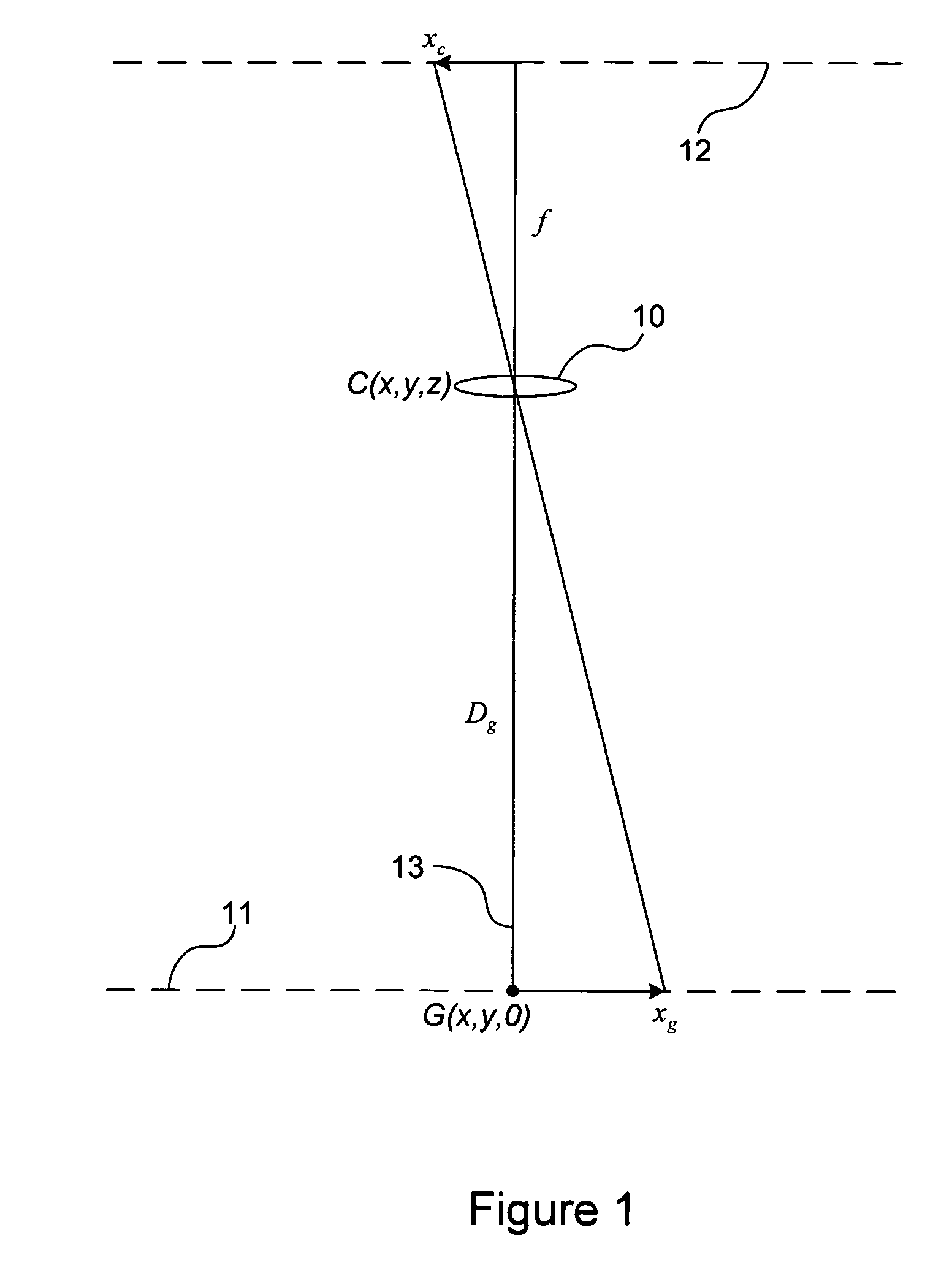
[0027]In order to describe the geometric transformations involved in geo-rectification, FIG. 1 shows the simple case of first-order transverse imaging of a planar object surface that is perpendicular to the optical axis, onto the real image plane of a camera. In particular, FIG. 1 shows a camera system, represented by lens 10, located at a position C(x, y, z) in space, and staring in a nadir-looking direction along an optical axis 13 at a point G(x, y, 0) on the ground plane 11. The distance of the optical axis 13 between the lens 10 and the point G of the planar object is shown as Dg. If the focal length of the lens is f, and the distance between the lens 10 and a real image plane is Dc (not shown), then the thin lens equation is:

[0028]1f=1Dc+1Dg(1)

Furthermore, if we assume a perfect thin lens (i.e. neglecting the effects of optical aberrations) and assume that Dg>>f, then the real image distance Dc is approximately equal to the focal length f as follow...


PUM


Abstract

A method of performing real-time geo-registration of high-resolution digital imagery using existing graphics processing units (GPUs) already found in current personal computers, rather than the main central processing unit (CPU). Digital image data captured by a camera (along with inertial navigation system (INS) data associated with the image data) is transferred to and processed by the GPU to perform the calculations involved in transforming the captured image into a geo-rectified, nadir-looking image. By using the GPU, the order-of-magnitude increase in throughput over conventional software techniques makes real-time geo-registration possible without the significant cost of custom hardware solutions.

Description

I. CLAIM OF PRIORITY IN PROVISIONAL APPLICATION[0001]This application claims the benefit of U.S. provisional application No. 60 / 651,839 filed Feb. 9, 2005, entitled, “Real-Time Geo-Registration of Imagery Using Commercial Off-the-Shelf Graphics Processors” by Laurence M. Flath et al.[0002]The United States Government has rights in this invention pursuant to Contract No. W-7405-ENG-48 between the United States Department of Energy and the University of California for the operation of Lawrence Livermore National Laboratory.II. FIELD OF THE INVENTION[0003]The present invention relates to geo-registration methods, and more particularly relates to a method of performing real-time geo-registration of high-resolution digital imagery using existing graphics processing units (GPUs) already available with current personal computers.III. BACKGROUND OF THE INVENTION[0004]A wide range of sensor technologies (visible, infrared, radar, etc.) and a wide variety of platforms (mountaintops, aircraft,...

Claims


Application Information

Patent Timeline
Patent Type & Authority Patents(United States)
IPC IPC(8): G06K9/00H04N7/18
CPCG06T5/006G06T7/0026G06T7/32
Inventor FLATH, LAURENCE M.KARTZ, MICHAEL W.
Owner LAWRENCE LIVERMORE NAT SECURITY LLC
Why Eureka
Try Eureka