Linear illumination lens with Fresnel facets

a technology of fresnel facets and illumination lenses, which is applied in the field of linear illumination lenses with fresnel facets, can solve the problems of generating non-uniformities, affecting the illumination uniformity of the target plane, so as to reduce the amount of deflection, reduce losses, and minimize aberrations

Active Publication Date: 2009-07-14
SEOUL SEMICONDUCTOR
View PDF22 Cites 208 Cited by
  • Summary
  • Abstract
  • Description
  • Claims
  • Application Information

AI Technical Summary

Benefits of technology

[0008]A need exists for a linear Fresnel lens specifically intended for illumination of nearby planar targets. The need is met by the embodiments of a linear Fresnel lens disclosed herein in which the angles of the individual Fresnel facets are selected to provide a uniform illumination of shelves arranged in planes perpendicular to the linear array of LEDs. The illumination lenses handle large amounts of out-of-plane light. Unlike conventional Fresnel lens designs, which are concerned with image fidelity, the linear illumination lenses disclosed herein rely on the principles of non-imaging optics, which are primarily concerned with flux distribution, in order to provide uniform illumination. As used herein, uniform illumination is defined as the absence of image information. For example, human vision is easily disturbed by abrupt departures from illumination uniformity, such as, for example, dark shadows or ribbons of glare.
[0010]Apparatuses and methods in accordance with aspects of the present invention relate generally to illumination by a line of light-emitting diodes (LEDs), and relate more particularly to linear lenses that enable such a line of LEDs to provide uniform illumination for large nearby targets, particularly display shelves and other such planar zones of illumination. The same illumination pattern is also useful for LEDs that replace the ubiquitous fluorescent tube in commercial and industrial buildings, which has recently become possible by increases in the efficacy and luminosity of commercially available LEDs. The embodiments disclosed herein provide uniform illumination in situations where conventional lighting is problematic, such as providing illumination over very wide angles of presentation by a 30″ shelf only 6″ from the light source. Such a situation is found within a typical large display refrigerator or freezer in a supermarket. In conventional systems using fluorescent lamps, the illumination is very uneven, which results in portions of a shelf being dark between lamps and other portions being over-illuminated close to each lamp.
[0016]The ray-deflection provided by a lens can be apportioned differently to the two surfaces of the lens. In the prior smooth lens method, each surface of the lens provides half of the total deflection in order to minimize aberrations. In lenses that must provide large deflections, however, the outer surface of the lens can terminate out-of-plane rays because of total internal reflection (TIR) and can deflect other rays in wrong directions. To reduce losses, the inner surface of the lens can be configured to provide more than half of the amounts of any large deflections, thus reducing the amounts of the deflections that need to be provided by the more vulnerable outer surface. Moreover, small deflections (under 10 degrees) can be assigned entirely to one surface of the lens. In accordance with the method disclosed herein, the assignment of portions of the total deflection amount to the inner surface and the outer surface varies across the lens, in contrast to the prior smooth lens method that configured the lens to provide approximately 50 percent of the total deflection at each of the inner lens surface and the outer lens surface.
[0017]In accordance with preferred embodiments disclosed herein, the Fresnel facets are provided only on one of the two lens surfaces, with interior facets usually imposing a gradual loss of flux. When ray deflections must be large, however, dual faceting may be warranted if the interior facets help reduce the TIR losses of out-of-plane rays at the outer surface.
[0021]When used as light sources, each of the above-described LEDs has a different off-axis distribution of intensity, and thus presents a somewhat different type of optimum illumination task. With linear lenses, the distribution of the illumination from a line of sources operates as a sum of many circular sources. If the LEDs have a restricted angular distribution, each point on the lens only receives light from a portion of the entire length. This effect is advantageous for linear lenses because the restricted angular distribution reduces the quantity of out-of-plane rays, which are harder for a linear lens to control. Regardless of the angular width of the illumination target of a linear lens, the preferred LED source is the LED source with the closest width. In the cases of close and thus wide-angle targets, a wide angle source will be desirable. In such cases, a tailored dome placed on the LED packages advantageously optimizes the performance of the linear lens. Because of the small size and high production volumes of LED packages, this would in practice be limited to domes configured as ellipsoids with the long axis of the ellipsoid oriented transversely. However, the linear lenses disclosed herein are intended to avoid any need to include secondary optics on the individual LEDs.
[0024]In a third step, the preferred method makes fine adjustments to the angles of the Fresnel facets to move the patterns from selected facets toward the darkest part of the overall pattern and away from the brightest part of the overall pattern. The third step also adjusts the individual contours of selected facets to widen the illumination patterns produced by the selected facets so that the illumination patterns overlap to eliminate streaks in the otherwise uniform output.

Problems solved by technology

For example, human vision is easily disturbed by abrupt departures from illumination uniformity, such as, for example, dark shadows or ribbons of glare.
In conventional systems using fluorescent lamps, the illumination is very uneven, which results in portions of a shelf being dark between lamps and other portions being over-illuminated close to each lamp.
Absent the disclosed method, when large bend angles are required for light arriving at a location on the lens from a distant LED in the array, the source image becomes curved, which sends light to the wrong part of the target plane and generates non-uniformities.

Method used


Image

  • Linear illumination lens with Fresnel facets
  • Linear illumination lens with Fresnel facets
  • Linear illumination lens with Fresnel facets

Examples


Embodiment Construction

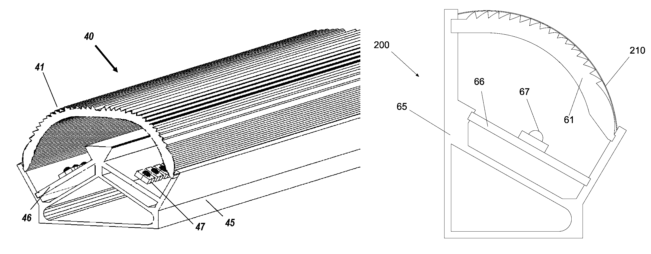
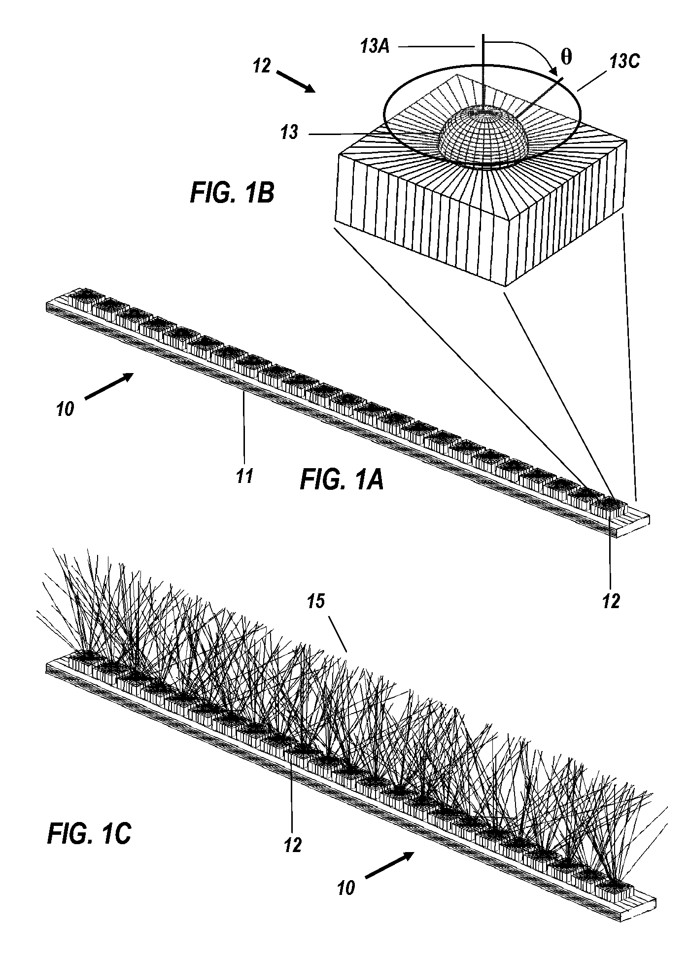
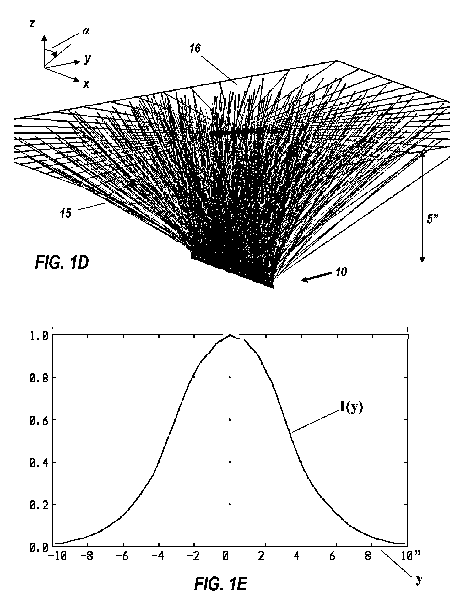
[0057]A long linear light source, such as a fluorescent tube, or a line of compact light sources such as LEDs, have a large fraction (e.g., often more than half) of the total lamp-flux produced by the source propagating as significantly out-of-plane rays when considered relative to a reference plane, normal to the length of the source. As illustrated below, the light source disclosed herein is a linear array of LEDs that have a longitudinal axis. The LEDs are positioned beneath an extruded linear lens that has a longitudinal lens axis, which is parallel to the array's longitudinal axis. The lens has a cross-sectional profile defined in a reference plane orthogonal to the lens axis and orthogonal to the array's longitudinal axis. The cross-sectional profile of the lens is linearly swept in the direction of the lens axis to create the linear lens in a desired length. The system and method disclosed herein for a linear lens may be utilized to produce a large lens in a circle instead of...


PUM


Abstract

A linear Fresnel lens for LED illumination is configured initially by using a meridional flux-assignment method and is then corrected by assessing the three-dimensional flux distribution of individual facets. The facet angles are slightly altered as required to produce uniformity. A variety of specialized lens shapes are generated, such as for illuminating shelves in commercial refrigerator food-display cases. The lens shapes are suitably thin for economical production by extrusion.

Description

RELATED APPLICATIONS[0001]The present application claims the benefit of priority under 35 U.S.C. § 119(e) to U.S. Provisional Application No. 60 / 941,388, filed on Jun. 1, 2007.BACKGROUND OF THE INVENTION[0002]1. Field of the Invention[0003]The following disclosure and the appended claims are directed to a lens for distributing light from a plurality of linearly arranged point light sources.[0004]2. Description of the Related Art[0005]Light emitting diodes (LEDs) are rapidly entering the general illumination market, because of their ever-decreasing prices and ever-increasing luminous efficacy, as well as their compactness, ruggedness, and long operating life. The expanding market for LEDs as illumination sources will generate enormous national energy savings, as well as significant waste reduction from the elimination of short-lived and relatively bulky light-bulb discards. The compactness of LEDs enables precision plastic optics to be economically manufactured and integrated into li...

Claims


Application Information

Patent Timeline
Patent Type & Authority Patents(United States)
IPC IPC(8): F21V5/00
CPCA47B97/00A47F3/001A47F3/04F21S4/008F21V5/02F21V5/045F21Y2103/003F21V33/0012F21W2131/305F21W2131/405F21Y2101/02F21S4/28F21Y2103/10F21Y2115/10
Inventor PARKYN, WILLIAM A.PELKA, DAVID G.
Owner SEOUL SEMICONDUCTOR
Why Eureka
Try Eureka