Vacuum pump

a vacuum pump and pump body technology, applied in the field of vacuum pumps, can solve the problems of significant increase in data processing load, increase in cost, and complexity of signal processing of each sensor signal, and achieve the effect of facilitating the reduction of size and cost of the signal processing circui

Active Publication Date: 2009-07-21
SHIMADZU CORP
View PDF5 Cites 26 Cited by
  • Summary
  • Abstract
  • Description
  • Claims
  • Application Information

AI Technical Summary

Benefits of technology

[0031]In view of the above circumstances, it is an object of the present invention to provide a magnetic bearing system capable of facilitating reductions in size and cost of a signal processing circuit for processing each sensor signal.
[0032]It is another object of the present invention to provide a magnetic bearing system capable of suppressing instability in a magnetic bearing control due to a temperature rise of a rotor assembly.
[0033]In order to achieve the above objects, a magnetic bearing system of the present invention is fundamentally designed to drive each of a plurality of sensors provided in the system by a common carrier wave, and sample a sensor signal from each of the sensors in synchronization with the carrier wave while using a common circuit, so as to facilitate reductions in size and cost of a signal processing circuit.

Problems solved by technology

Thus, a size of the signal processing circuits becomes larger to cause an increase in cost.
The high-speed sampling will lead to complexity in signal processing of each sensor signal and significant increase in data processing load.
If the sampling interval is extended while keeping the carrier wave at a constant frequency, the signal processing load can be reduced, whereas the frequency of the carrier wave nonconforming to the sampling theorem will make it difficult to adequately extract each sensed signal from the sensor signals and accurately perform the magnetic bearing control such as the levitation control and the motor drive control, and the rotor temperature monitoring.
Moreover, the high-speed sampling requires a device capable of high-speed processing which leads to an increase in cost.
Further, the conventional magnetic bearing system has a problem about instability in a magnetic bearing control due to a temperature rise of a rotor assembly (i.e., rotor, rotary shaft, target member, rotor disc, etc.). FIGS. 19A to 19C are graphs for explaining relationships between a temperature rise of the rotor assembly and respective magnetic bearing control parameters.
As shown in FIG. 19C, if the output of the position sensor becomes higher, a loop gain of the magnetic bearing control circuit is likely to be excessively increased to cause instability in the magnetic bearing control.
Due to the above relationship, the loop gain of the magnetic bearing control circuit becomes higher along with an increase in temperature of the rotor assembly to cause the problem about instability in the magnetic bearing control.
Further, if the vacuum pump is continuously operated even after the rotor is placed in a high-temperature state, resulting negative factors due to thermal expansion, such as permanent deformation and looseness in each portion of the rotor, are likely to cause a problem about occurrence of shaft vibration.

Method used


Image

  • Vacuum pump
  • Vacuum pump
  • Vacuum pump

Examples


Embodiment Construction

[0074]With reference to the drawings, an exemplary embodiment of the present invention will now be described.

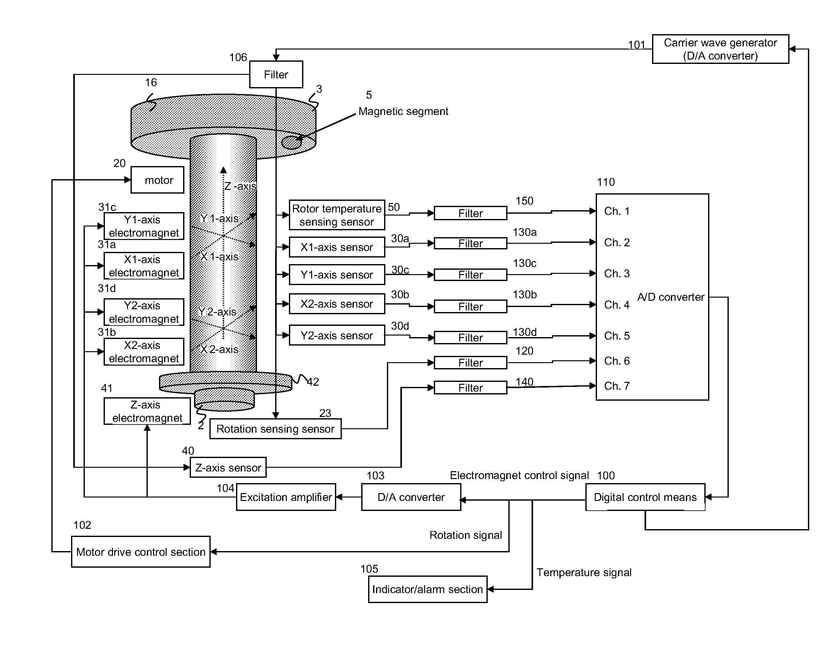
[0075]FIG. 1 is a block diagram showing a control circuit of a magnetic bearing system according the present invention. In FIG. 1, only a part of the control circuit relating to the present invention is illustrated, and the remaining part is omitted. Further, the same element or component as that in FIG. 18 is defined by the same reference numeral or code, and a reduplicated description thereabout will be fundamentally omitted.

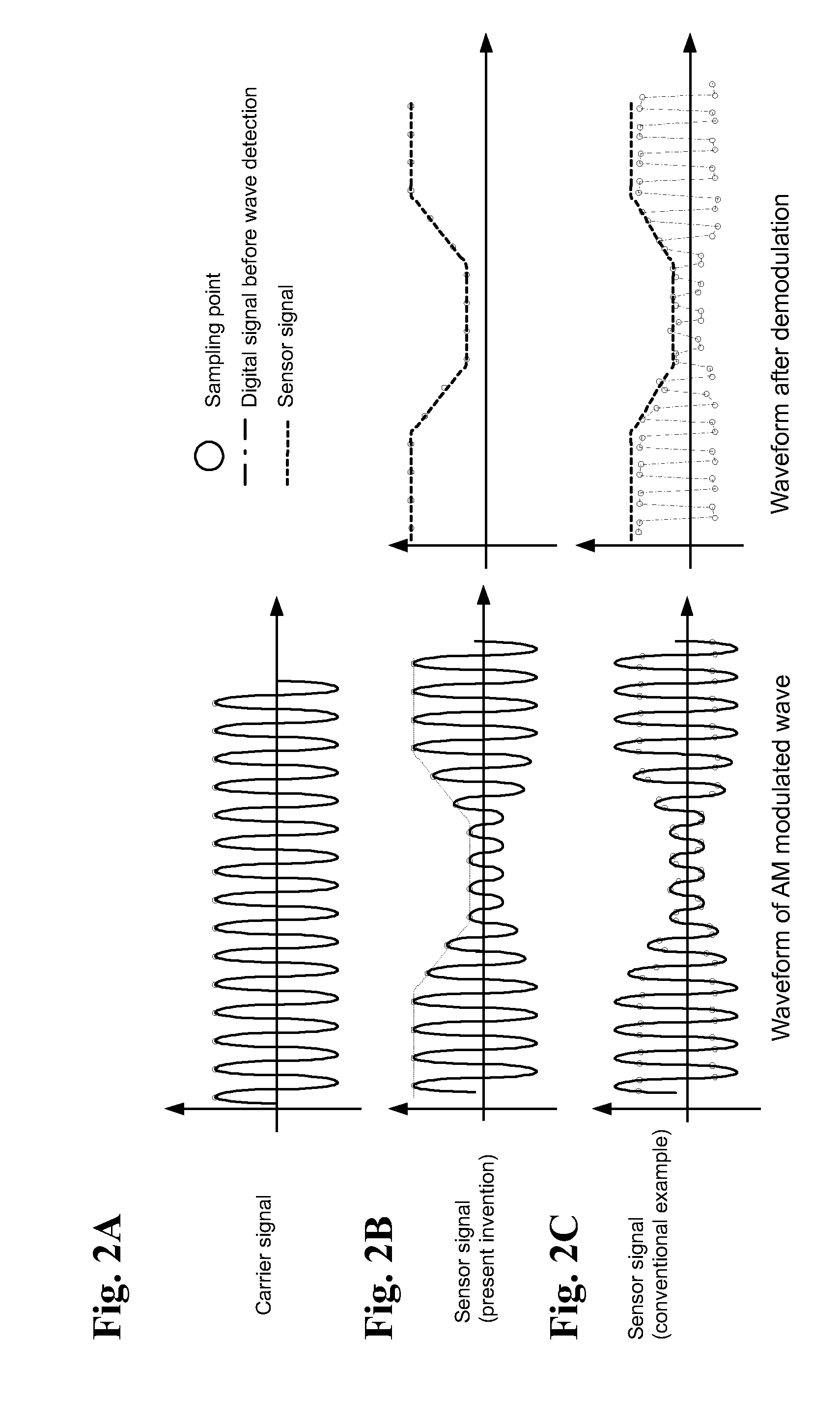
[0076]With reference to FIGS. 2A to 10, a control circuit of the magnet bearing system according to the present invention will be described which is designed to drive a plurality of sensors provided in the magnetic bearing system by a common carrier wave and sample respective sensor signals from the sensors in synchronization with the carrier wave so as to facilitate lowering of a sampling frequency and use of a common signal processing circuit. Then, w...


PUM


Abstract

A magnetic bearing system for use in a vacuum pump including a motor provided with a rotary blade. The magnetic bearing system including a rotary shaft rotationally holding said rotor, a motor for rotationally driving said rotary shaft, a magnetic levitation section for supporting said rotor relative to a stator through said rotary shaft in a non-contact manner, a rotation detection section for detecting a rotational speed of said rotor, a rotor-temperature detection section for detecting a temperature of said rotor; a carrier-wave generation section for supplying a common carrier wave to each of a plurality of sensors provided in said magnetic levitation section, said rotation detection section and said rotor-temperature detection section, and an A / D conversion section for sampling a sensor signal output from each of said sensors, in synchronization with said carrier wave.

Description

BACKGROUND OF THE INVENTION[0001]1. Field of the Invention[0002]The present invention relates to a vacuum pump, such as a turbo-molecular pump, and more particularly to a magnetic bearing system for supporting a rotary shaft of a vacuum pump in a non-contact manner.[0003]2. Description of the Related Art[0004]In vacuum apparatuses, a suction or evacuation mechanism, such as a turbo-molecular pump, is used for sucking or evacuating gas from a vacuum vessel or the like to produce a vacuum therewithin. Generally, a turbo-molecular pump is equipped with a pump unit having a stator and a rotor, and designed to rotationally drive the rotor by an electrically-driven motor to suck / evacuate gas from a vacuum vessel or the like.[0005]In most types of the vacuum pumps, such as a turbo-molecular pump, a rotary shaft rotationally holding the rotor is supported by a magnetic bearing system which comprises a position sensor and an electromagnet each installed between a pump casing and the rotary s...

Claims


Application Information

Patent Timeline
Patent Type & Authority Patents(United States)
IPC IPC(8): H01H47/00
CPCF16C32/0446F16C32/0455F16C2360/44F16C2360/45
Inventor KOZAKI, JUNICHIROOHFUJI, MASAKIMORIYAMA, NOBUHIKO
Owner SHIMADZU CORP
Why Eureka
Try Eureka