Method and apparatus for body position monitor and fall detect ion using radar

Active Publication Date: 2009-07-28
THE OSTERWEIL FAMILY TRUST
View PDF32 Cites 172 Cited by
  • Summary
  • Abstract
  • Description
  • Claims
  • Application Information

AI Technical Summary

Benefits of technology

[0033]According to another object of the invention, a method is disclosed for monitoring a position of a subject in a predetermined volume. Each radar or cluster operates autonomously in monitoring a subject (cluster is discussed further later). When the coverage area exceeds the capacity of one radar cluster more radar clusters are used. Handover of monitoring from one radar cluster to another is determined by the physical location of the monitored subject and signal strength related to the beating heart and/or lung movements at one radar cluster compared to an adjacent radar cluster where the beating heart and/or lung movement signals are dominant. This roaming handover is coordinated in a systematic manner similar to cell phone roaming techniques.
[0034]The radar cluster performance is further enhanced by post installation calibration. Such calibration provides correction data for strategic points of the monitored premises such as, but not limited to, room corners at floor level, center of the room at floor level, doorways, etc. Virtual mapping of the premises obtained from such calibration enhances system's tracking capability of a subject.
[0035]Another advantage of the invention includes a static signature of the reflected signal stored as reference for each radar cluster. A change in signature could be an indication that a subject entered the monitored space for the given radar cluster and therefore a search for a chest is launched. If none is found, the radar cluster assumes a standby state and stor

Problems solved by technology

People who are elderly, infirm, chronically ill, confused, or are otherwise unable to care for themselves and very often fall with resulting medical distress, often reside in a nursing home or similar type institution.
Similarly, others who find that living alone is unacceptably difficult or risky may elect to reside in an assisted living facility, or the like, that assists their residents in the performance of certain daily living tasks (such as, for example, bathing and dressing).
In a typical assisted living or nursing home, a limited number of staff members are available to monitor a relatively large number of residents (or patients).
In such a situation, the required rapid response might not be timely, due to the unavailability of an attendant.
In the absence of the required rapid response, serious injury, or

Method used


Image

  • Method and apparatus for body position monitor and fall detect ion using radar
  • Method and apparatus for body position monitor and fall detect ion using radar
  • Method and apparatus for body position monitor and fall detect ion using radar

Examples


Example

[0063]The particulars shown herein are by way of example and for purposes of illustrative discussion of embodiments of the present invention only and are presented in the cause of providing what is believed to be the most useful and readily understood description of the principles and conceptual aspects of the present invention. In this regard, no attempt is made to show details of the present invention in more detail than is necessary for the fundamental understanding of the present invention, the description taken with the drawings making apparent to those skilled in the art how the present invention may be embodied in practice.

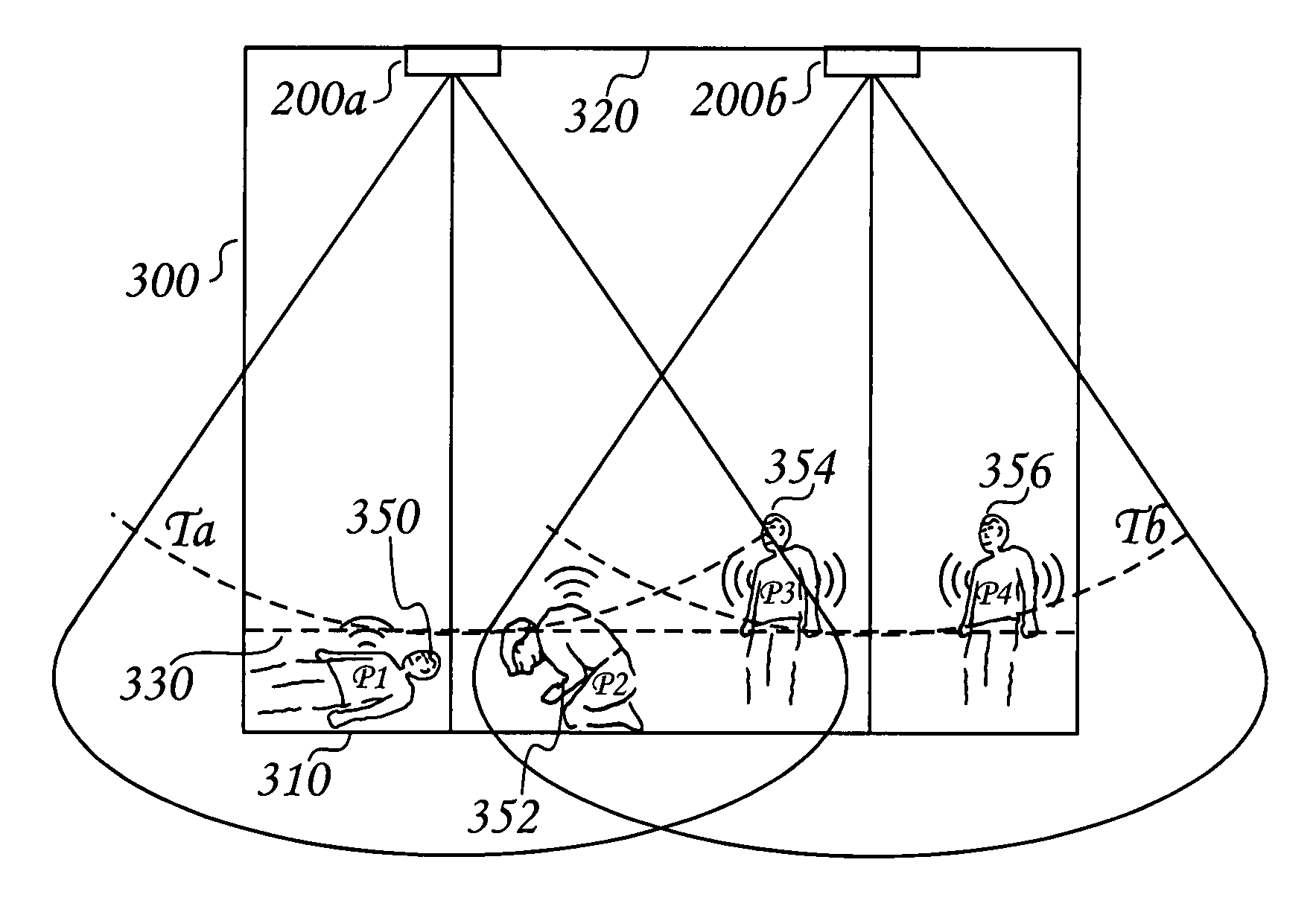
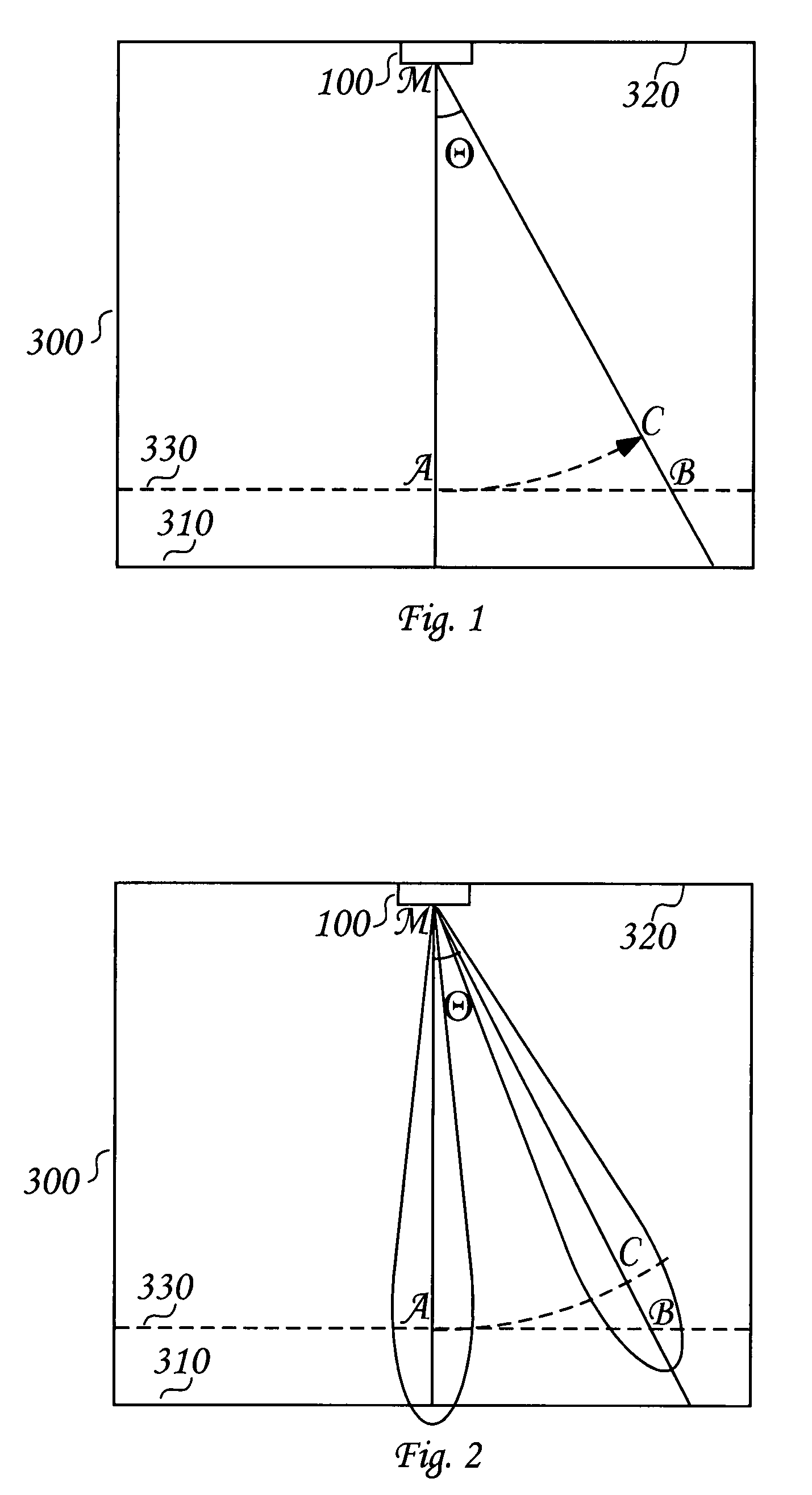
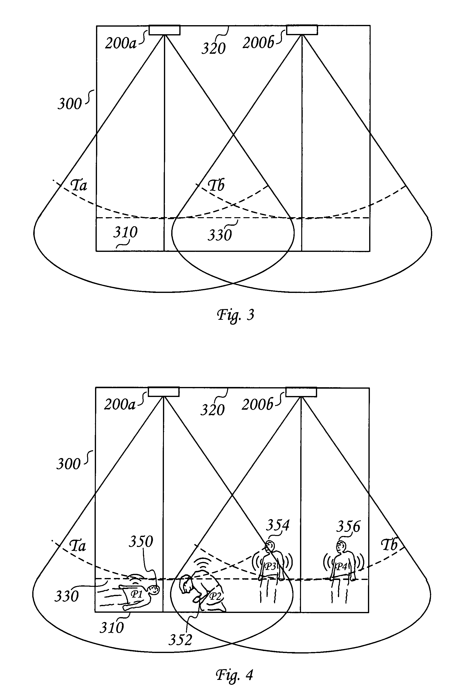
[0064]The present invention is a fall detector based on a quantitative spatial analysis of a subject 350 in a monitored volume (i.e., in close proximity, such as, for example, a room 300 and / or corridor—see FIG. 6 and FIG. 11) and the processing of the captured image to determine physical characteristics and other features of a monitored individual. In this...


PUM


Abstract

A radar fall detector system. The radar fall detector system includes transmitter and receiver antennae and a signal processor that processes a reflected signal. Doppler analysis of the reflected signal determines a subject's moving body segment and its distance to a floor.

Description

RELATED DATA[0001]The present application expressly incorporates by reference herein the entire disclosure of U.S. Provisional Applications Nos. 60 / 795,277, entitled “Method and apparatus for a three-dimensional positioning system using Ultra-Wideband radar”, which was filed on Apr. 27, 2006 and 60 / 831,063, entitled “Method and apparatus for a body position monitor and fall detector using Ultra-Wideband radar” which was filed on Jul. 17, 2006.FIELD OF THE INVENTION[0002]The present invention is directed to an apparatus and method for automatically identifying a subject, such as, for example, a human or animal, who has fallen while in a defined three-dimensional (3-D) space, determining the physical position of the subject, and evaluating the position with respect to particular assessment criteria. More specifically, the present invention relates to the use of radar including generation and subsequent analysis radar return signals to determine whether the data correlates to a conditi...

Claims


Application Information

Patent Timeline
IPC IPC(8): G01S13/00A61B5/05G01S13/58G01S3/02G08B23/00A61B8/00
CPCA61B5/1117G01S13/56G08B25/001G08B21/043G08B21/0469G08B21/22G01S13/886G01S13/878
Inventor OSTERWEIL, JOSEF
Owner THE OSTERWEIL FAMILY TRUST
Why Eureka
Try Eureka