
Multi-component fuel cell gasket for low temperature sealing and minimal membrane contamination

a fuel cell and gasket technology, applied in the field of fuel cells, can solve the problems of degrading the gasket, reducing the service life of the gasket,

Inactive Publication Date: 2009-08-04
GM GLOBAL TECH OPERATIONS LLC
View PDF26 Cites 2 Cited by
  • Summary
  • Abstract
  • Description
  • Claims
  • Application Information

AI Technical Summary

Benefits of technology

The present invention provides a fuel cell with improved sealing performance. The fuel cell includes first and second bipolar plate members, diffusion medium members, a membrane electrode assembly member, and first and second seal members. The first seal member is made of a chemically inert material and is positioned in an inboard position relative to the bipolar plate members. The second seal member is made of a silicone material and is positioned in an outboard position relative to the bipolar plate members. The seal members are designed to provide a sealing function with a leak rate no greater than 0.01 standard cubic centimeters per minute per centimeter of linear seal length. The fuel cell also includes a carrier member made of polyimide material to support the seal members. The technical effect of the invention is to improve the sealing performance of the fuel cell and to provide a more reliable and efficient sealing solution.

Problems solved by technology

The catalytic particles are typically costly precious metal particles.
These membrane electrode assemblies are relatively expensive to manufacture and require certain conditions, including proper water management and humidification, and control of catalyst fouling constituents such as carbon monoxide (CO), for effective operation.
These contaminants are believed to poison the catalysts and proton-conduction sites of the membranes, and degrade the gasket.
One significant drawback, however, is that EPDM, with its higher glass transition temperature, has been shown to not seal as well, especially at relatively cold temperatures.

Method used


Image

  • Multi-component fuel cell gasket for low temperature sealing and minimal membrane contamination
  • Multi-component fuel cell gasket for low temperature sealing and minimal membrane contamination
  • Multi-component fuel cell gasket for low temperature sealing and minimal membrane contamination

Examples


Embodiment Construction

[0017]The following description of the preferred embodiment(s) is merely exemplary in nature and is in no way intended to limit the invention, its application, or uses.

[0018]The present invention proposes the use of two or more materials as a gasket for use in conjunction with fuel cells.

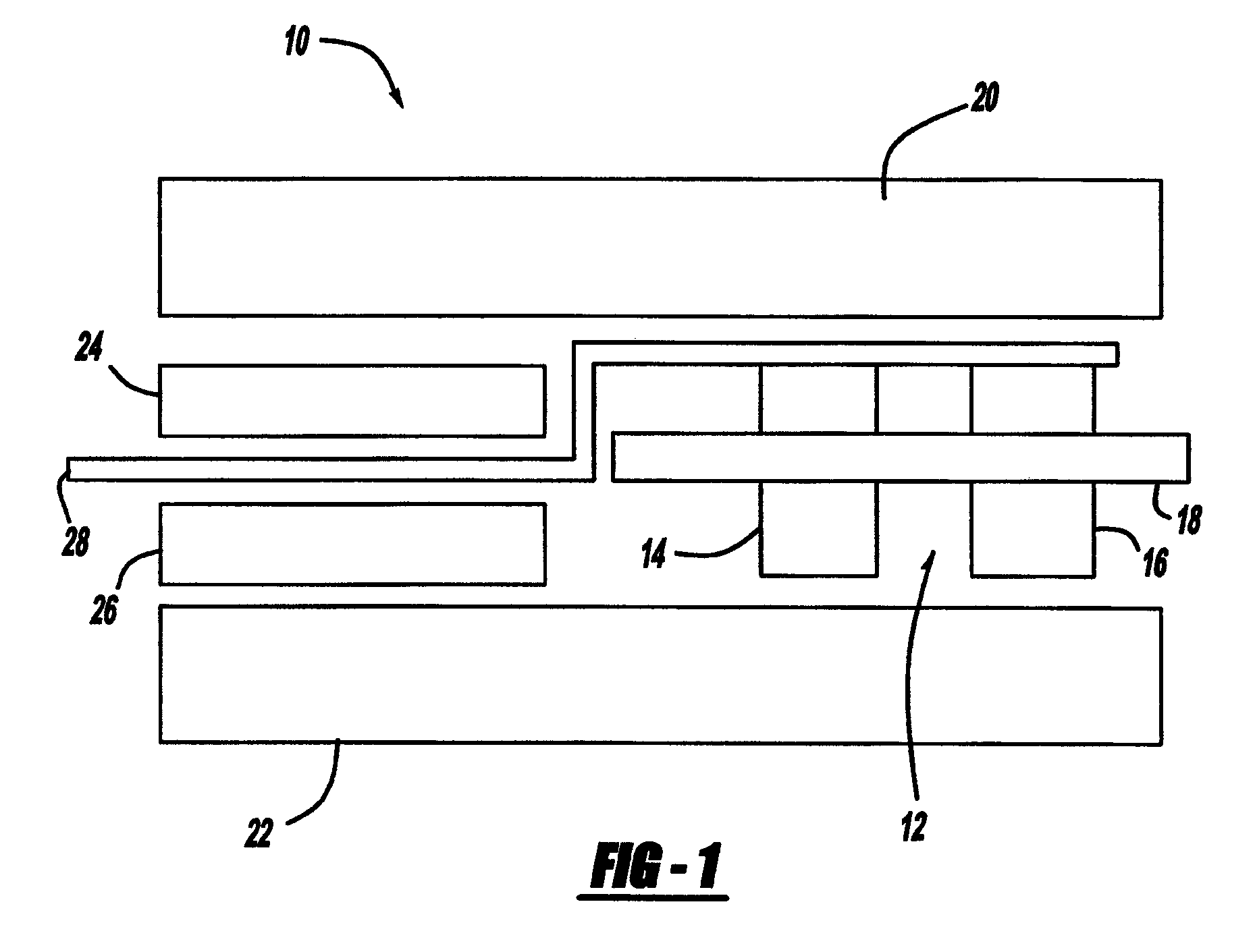
[0019]In accordance with one aspect of the present invention, ethylene propylene diene monomer (EPDM) and / or the like, or another more chemically inert gasket material, is located in an inboard position and is the wetted material that is exposed to the fuel cell operating environment.

[0020]In accordance with another aspect of the present invention, silicone and / or the like, or another contaminating material with better cold-sealability is located in an outside or outboard position and does not come in contact with the fuel cell internal environment.

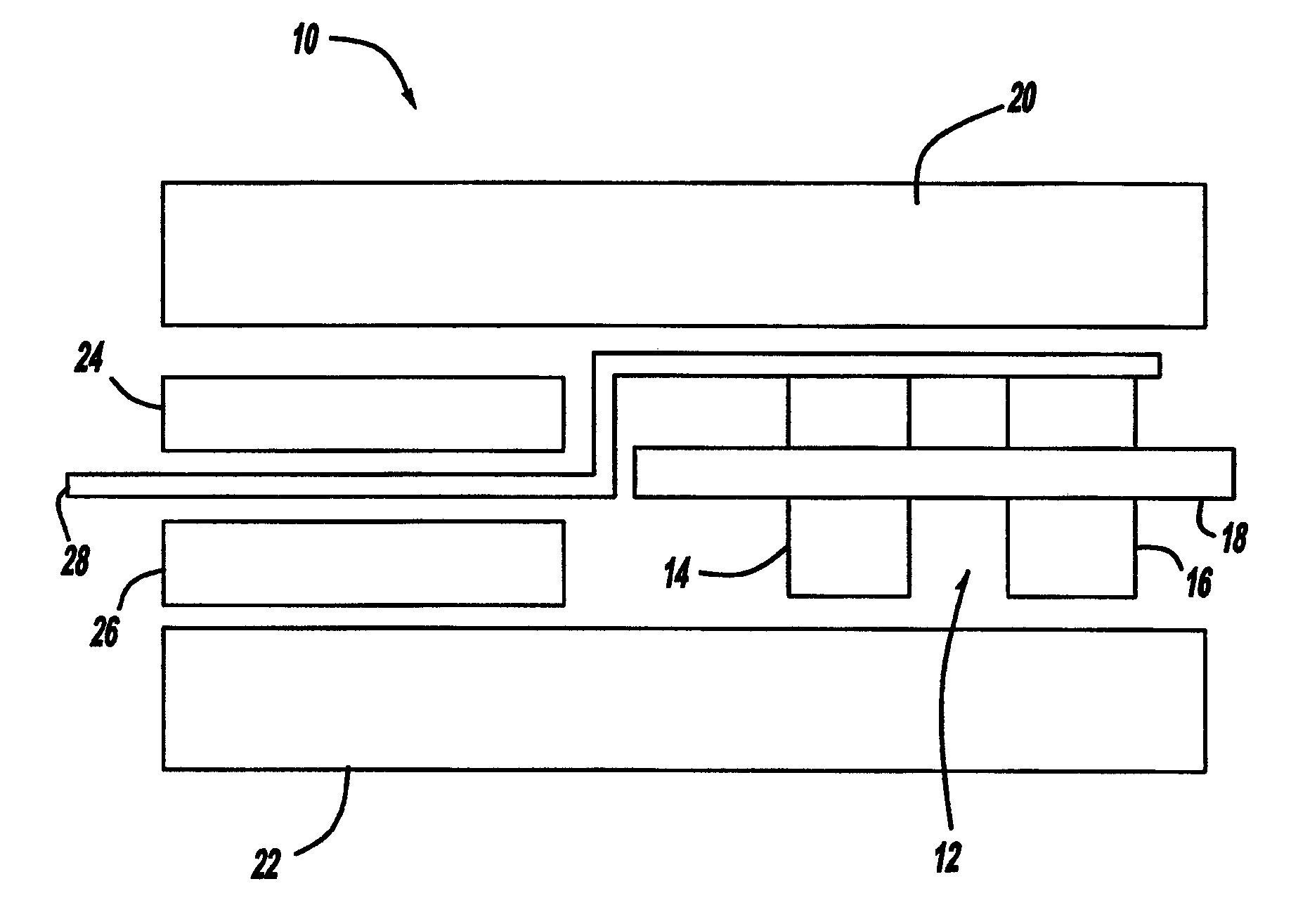
[0021]Referring to FIG. 1, there is shown a schematic view of a fuel cell 10 having a gasket 12 in accordance with the general teachings of the present i...


PUM

PropertyMeasurementUnit
temperatureaaaaaaaaaa
chemically inertaaaaaaaaaa
lengthaaaaaaaaaa

Abstract

A gasket for a fuel cell, wherein the gasket includes the use of two or more different materials as the gasket. For example, ethylene propylene diene monomer (EPDM) and / or the like, or another more chemically inert gasket material, is located inside or on an inboard position and is the wetted material that is exposed to the fuel cell operating environment. Silicone and / or the like, or another potentially contaminating material with better cold temperature sealability, is located outside or on an outboard position and does not come in contact with the fuel cell internal environment. One method of constructing such a gasket would be two include two parallel bead traces of the gasket materials on a polyimide (e.g., KAPTON®) carrier, or the like.

Description

FIELD OF THE INVENTION[0001]The present invention relates generally to fuel cells, and more particularly to fuel cell gaskets that have enhanced low temperature sealing and membrane contamination resistance characteristics.BACKGROUND OF THE INVENTION[0002]Fuel cells have been used as a power source in many applications. For example, fuel cells have been proposed for use in electrical vehicular power plants to replace internal combustion engines. In proton exchange membrane (PEM)-type fuel cells, hydrogen is supplied to the anode of the fuel cell and oxygen is supplied as the oxidant to the cathode. PEM fuel cells include a membrane electrode assembly (MEA) comprising a thin, proton transmissive, non-electrically conductive solid polymer electrolyte membrane having the anode catalyst on one of its faces and the cathode catalyst on the opposite face. The MEA is sandwiched between a pair of electrically conductive elements, sometimes referred to as the gas diffusion media components, t...

Claims


Application Information

Patent Timeline
Patent Type & Authority Patents(United States)
IPC IPC(8): H01M2/08
CPCH01M8/0276H01M8/0284Y02E60/50H01M2008/1095H01M8/0273
Inventor THOMPSON, ERIC L.FLY, GERALD W.
Owner GM GLOBAL TECH OPERATIONS LLC
Learn More