Polymer composites for biomedical applications and methods of making

a biomedical and polymer technology, applied in the field of biomedical polymer composites, can solve the problems of high energy density, high localized heating of tissue that comes, perforation or ablation of the aneurysm wall,

Active Publication Date: 2009-08-04
DFINE INC
View PDF89 Cites 73 Cited by
  • Summary
  • Abstract
  • Description
  • Claims
  • Application Information

AI Technical Summary

Benefits of technology

[0007]In general, this invention comprises a vascular occlusion system for treating aneurysms that provides a novel class of polymer composite embolic elements that carry thin conductive coatings or conductive fillers to provide the composite with a specified resistivity to electrical current flow. The embolic element is introduced into a targeted site in a patient's vasculature by a microcatheter sleeve. The thin metallic coating allows the embolic element to be soft and flexible, and more importantly, allows the physician to select any desired length (and volume) of embolic element in vivo for causing mechanical occlusion of the aneurysm. The system of the invention also provides an electrical source and computer controller for feedback modulation of power delivery with a first (low) range and a second (high) range to accomplish two different methods of the invention. The electrical source is coupled to an electrode arrangement at the distal terminus of the catheter sleeve that contacts the surface of the embolic element as it is slidably deployed from the catheter. Thus, energy is delivered to resistive embolic element directly from the distal terminus of the catheter sleeve. The catheter working end also carries a thermocouple, coupled to feedback circuitry, for sensing the temperature of the deployed embolic element and controlling its temperature via power modulation.

Problems solved by technology

It is believed that several risk factors are involved in any uncontrolled use of significant levels of Rf energy to cause so-called electrothrombosis.
Most important, the use of electrical energy to cause current flow between a coil (first electrode) within an aneurysm and a ground (a second body electrode) will likely cause high energy densities and highly localized heating of tissue that comes into contact with the coil.
If the wall of the aneurysm contacts the energized portion of a coil, there is a significant danger of perforation or ablation of the aneurysm wall that could be life-threatening.
Further, the use of uncontrolled energy delivery to an implanted coil could heat adjacent brain tissue to excessive levels resulting in loss of brain function or even death.
However, it is still likely that unwanted localized heating will occur within the aneurysm sac when attempting to cause ohmic heating of the blood volume in an aneurysm by creating Rf current flow between an electrode coil and a body electrode.
Another disadvantage of using the typical commercially available wire coil is that the physician must estimate dimensions and volume of the aneurysm and then feed multiple coils into the aneurysm.
The deployment of each coil is time consuming, and the detachment of the coil from the introducer pushwire also is time consuming.

Method used


Image

  • Polymer composites for biomedical applications and methods of making
  • Polymer composites for biomedical applications and methods of making
  • Polymer composites for biomedical applications and methods of making

Examples


Embodiment Construction

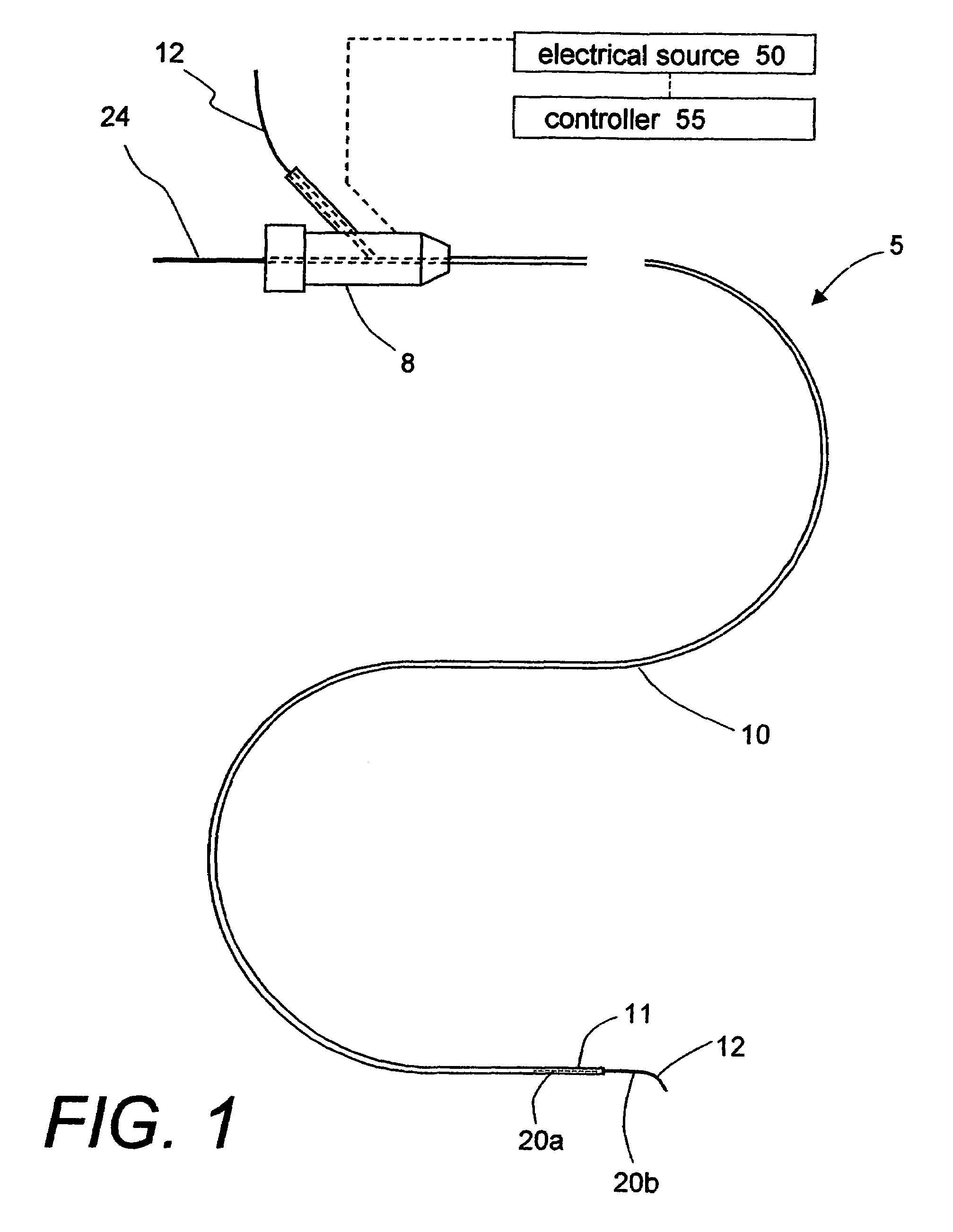
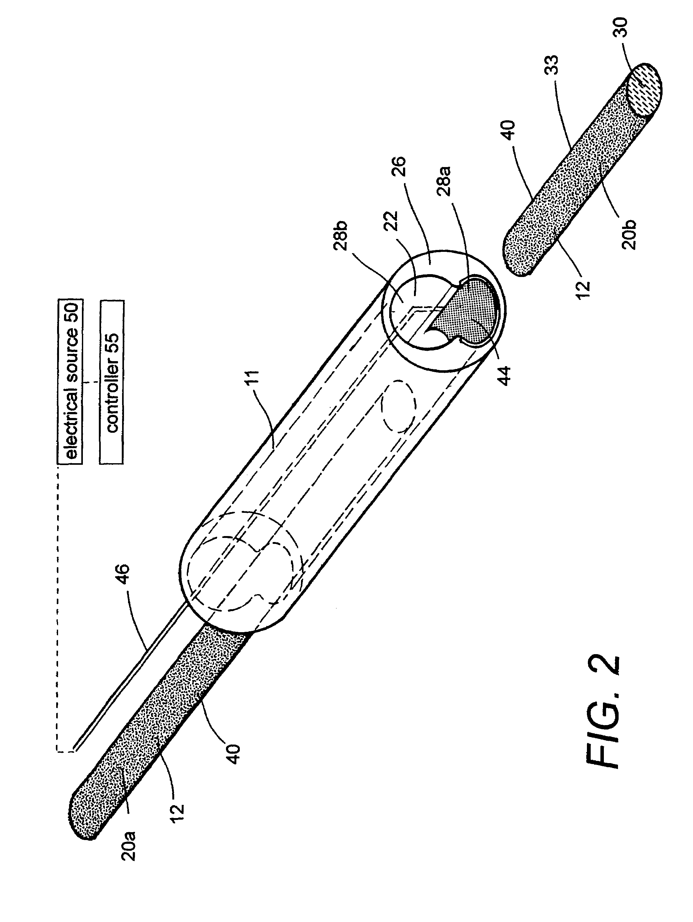
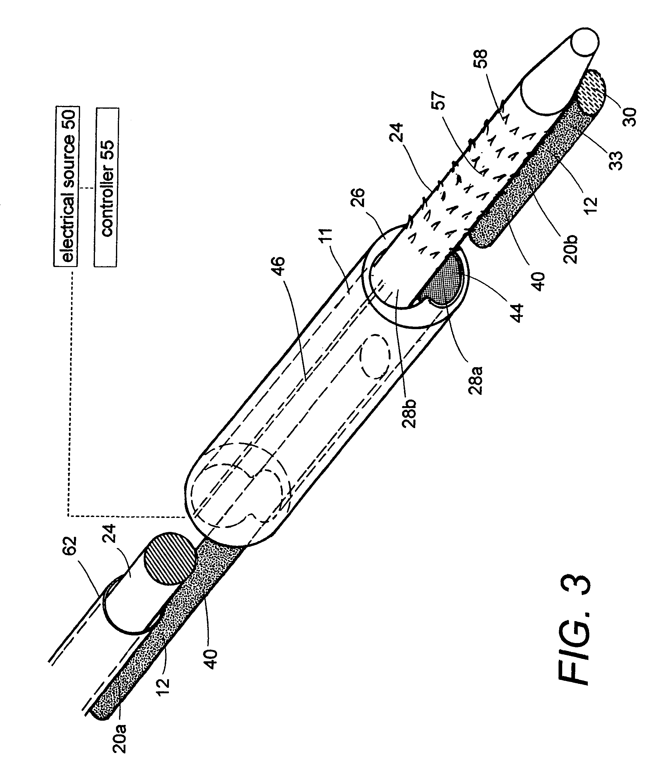
[0053]1. Type “A” embodiment of vascular occlusive system. FIG. 1 shows an elevational view of a Type “A” catheter system 5 for occluding an aneurysm or other vascular malformation. The catheter system has a proximal handle or manifold 8 as is known in the art that is coupled to an elongate microcatheter sleeve 10. FIG. 2 is a cut-away view of the working end 11 of catheter sleeve 10 that illustrates the metallic-coated elongate thread or filament element 12 corresponding to present invention that can be passed axially through the cooperating microcatheter sleeve 10. The flexible embolic element 12 defines a proximal portion 20a still carried within catheter sleeve 10 and a distal thread portion 20b that is pushed outward of the catheter. In this exemplary embodiment, the embolic element 12 has an oval or flattened cross-section, but other cross-sectional shapes are suitable.

[0054]In this exemplary embodiment, an internal bore or passageway 22 within the catheter sleeve 10 is adapte...


PUM

PropertyMeasurementUnit
total lengthaaaaaaaaaa
resistivityaaaaaaaaaa

Abstract

A biomedical polymer composite that exhibits ultra-low thermal conductivity properties. In a preferred embodiment, the biomedical polymer composite comprises a base polymer component with a dispersed thermally non-conductive filler component consisting of glass or ceramic nanospheres or microspheres that have a thermal conductivity of less than 5 W/m-K, and preferably less than 2 W/m-K. In one embodiment, the polymer composite is has an electrically conductive filler and can be used in a filament for treating arteriovascular malformations. In another embodiment, the polymeric composite can be used as an energy-coupling means to apply energy to tissue.

Description

CROSS-REFERENCE TO RELATED APPLICATION[0001]This application is a Continuation-In-Part of U.S. patent application Ser. No. 10 / 456,149 filed Jun. 5, 2003, now U.S. Pat. No. 6,958,061 titled “Microspheres with Sacrificial Coatings for Vaso-Occlusive Systems”, which is incorporated herein by this reference. This application is related to U.S. patent application Ser. No. 10 / 779,075 filed Feb. 14, 2004 titled “Polymer Composites and Methods of Making”, which is incorporated herein by this reference.FIELD OF THE INVENTION[0002]This invention relates to a biomedical polymer composite that exhibits ultra-low thermal conductivity properties as well as optional electrical resistivity. In one embodiment, the polymer composite is formed into an embolic filament for occluding an arteriovascular malformation (AVM) wherein electrical energy can be used to sacrifice, melt and divide any suitable length of the filament for filling the AVM without any collateral thermal effects within the vessel lume...

Claims


Application Information

Patent Timeline
Patent Type & Authority Patents(United States)
IPC IPC(8): C08J9/32D04H1/00
CPCA61B17/12022A61B17/12113A61B17/12118A61B17/12136A61B17/12168A61B17/12181A61B17/12186D04H1/42A61B17/1214A61B18/04A61B17/12045A61B2018/00589A61B2017/12068A61B2017/12072A61B2018/00416Y10T428/249924
Inventor TRUCKAI, CSABA
Owner DFINE INC
Why Eureka
Try Eureka