Fluid cooling system, cooled fluid dispenser comprising the later, and methods for sterilization thereof

a technology of fluid dispensers and cooling systems, which is applied in the direction of liquid dispensing, stationary tubular conduit assemblies, lighting and heating apparatus, etc. it can solve the problems of high cost of operation, cleaning or sterilization and maintenance, and the downtime of the machine during the cleaning or sterilization step is relatively high, so as to reduce the volume of heat transfer agents and effectively transmit thermal energy , the effect of releasing cooling energy over tim

Inactive Publication Date: 2009-08-11
DIEAUS
View PDF10 Cites 7 Cited by
  • Summary
  • Abstract
  • Description
  • Claims
  • Application Information

AI Technical Summary

Benefits of technology

[0009]Consequently, one advantage of the present invention is that the fluid cooling system can be integrated into any chilled fluid dispenser system, such as a drinking water dispenser. Furthermore, the fluid cooling system does not need to have a drainage pump, where sterilization of the fluid cooling system or cooled fluid dispenser is not required. This is optional in the event that sterilization of the circuit including the first conduit is desired, for example, in a drinking water dispenser, or for distributing oxygen in a respiratory assistance apparatus.
[0010]In a more preferred embodiment of the invention, the primary heat exchanger system is arranged at least partially, and more preferably substantially, within the secondary heat exchanger system. By the term “partially” or “substantially within”, it is meant that at least part, and preferably a major part, of the primary heat exchanger system is spatially located within the secondary heat exchanger system. This provides for a very compact fluid cooling system according to the invention and reduces the volumes of heat transfer agent that need to be circulated to obtain the desired cooling effect.
[0011]In one preferred embodiment of the present invention, the primary heat exchanger system comprises a chamber. The chamber is generally made of a plastic or metallic material, that will not deform or buckle under the operating temperatures or pressures, in particular in relation to the cold temperatures generated, and can be generally cylindrical in shape, although other shapes could be envisaged easily by the skilled person that would still be functional. The chamber is dimensioned to receive a coil, which coil serves to effect cooling thermal exchange with a heat transfer agent in the chamber of said primary heat exchanger system. It will be understood that other means of generating a cooling effect, for example, using a finger and the Pelletier effect, or equivalent means can be used, instead of the coil. Advantageously, the primary heat exchanger system also comprises a thermostat, that enables regulation of the temperature of the heat transfer agent, thereby controlling the volume of solid phase of the heat transfer agent that forms in the chamber. The terms “heat transfer agent” and “heat exchange agent” are used interchangeably in the present specification and claims and have the meaning as defined hereafter. By “heat transfer agent” or “heat exchange agent”, it is meant an agent that can effectively transmit its thermal energy to the fluid to be cooled and dispensed, preferably without the necessity for an important initial energy input. Preferred heat transfer agents are ones that undergo liquid/solid phase transition. Water is the preferred heat transfer agent in this case, since the ice formed by the coil when water in the chamber comes into contact with the coil tends to only thaw again slowly, thus releasing its cooling en

Problems solved by technology

One of the problems of the known systems is that the primary and secondary heat exchanger systems have to be quite voluminous in order to obtain the desired cooling effect of the liquid.
This limits their a

Method used


Image

  • Fluid cooling system, cooled fluid dispenser comprising the later, and methods for sterilization thereof
  • Fluid cooling system, cooled fluid dispenser comprising the later, and methods for sterilization thereof
  • Fluid cooling system, cooled fluid dispenser comprising the later, and methods for sterilization thereof

Examples


example 1

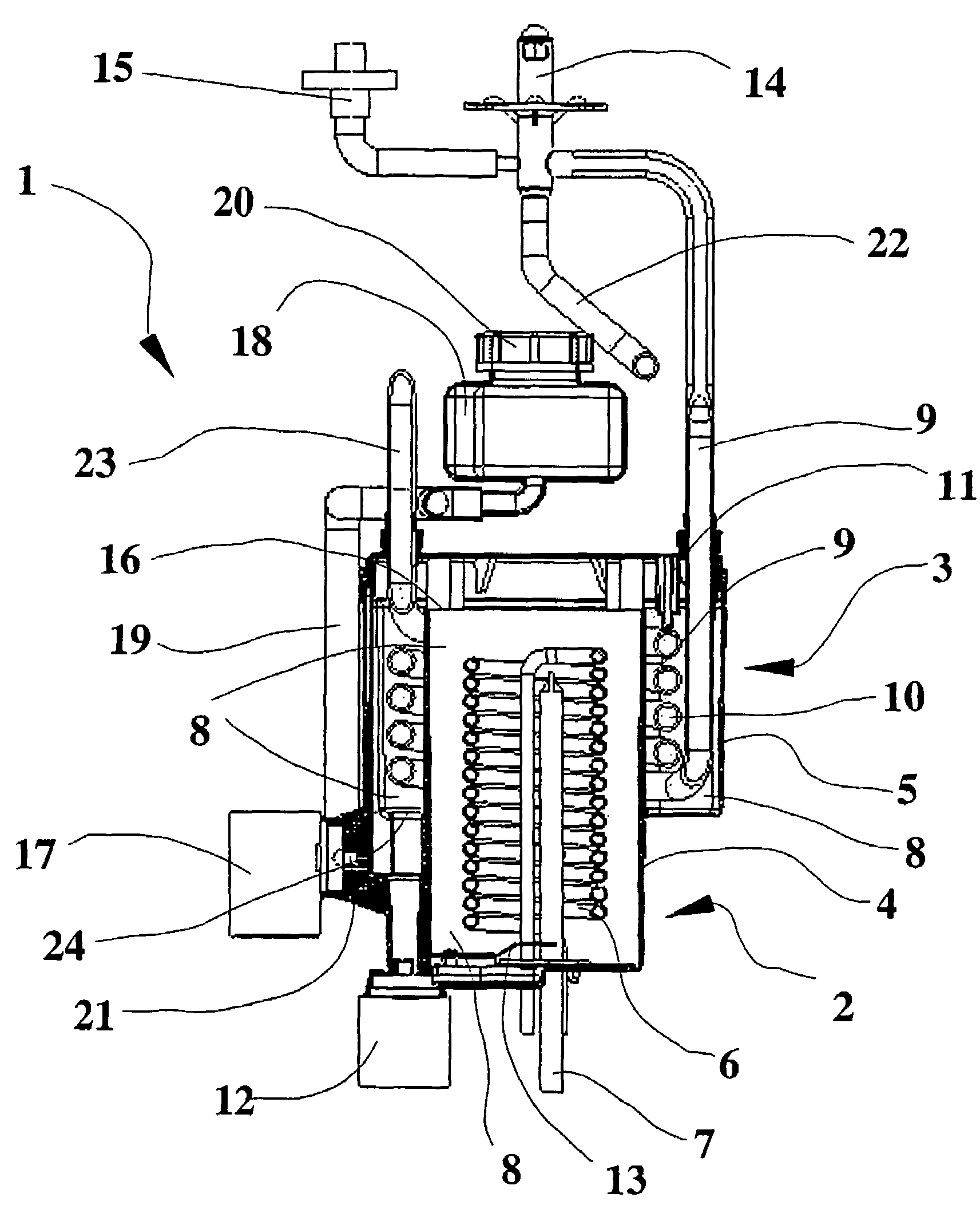
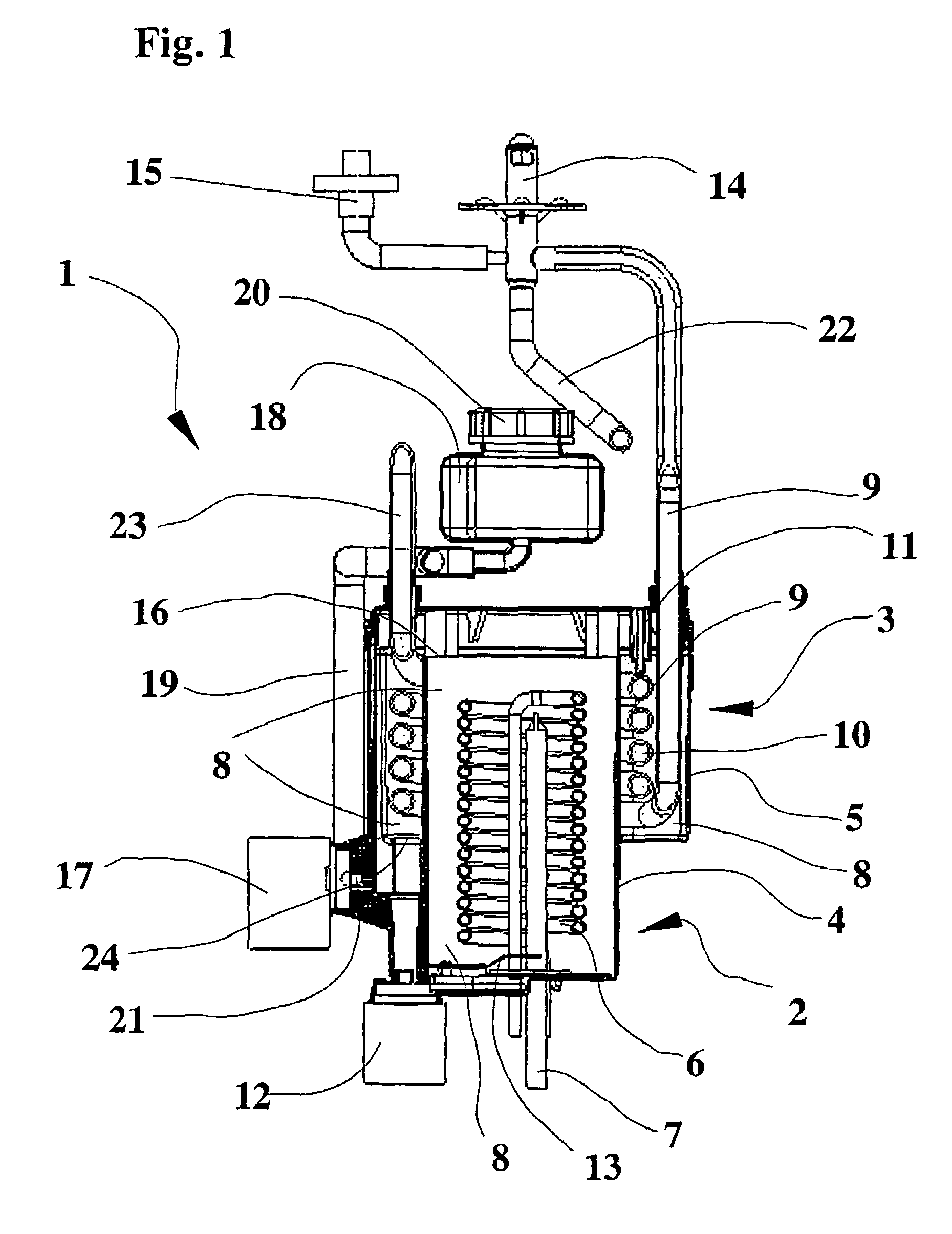
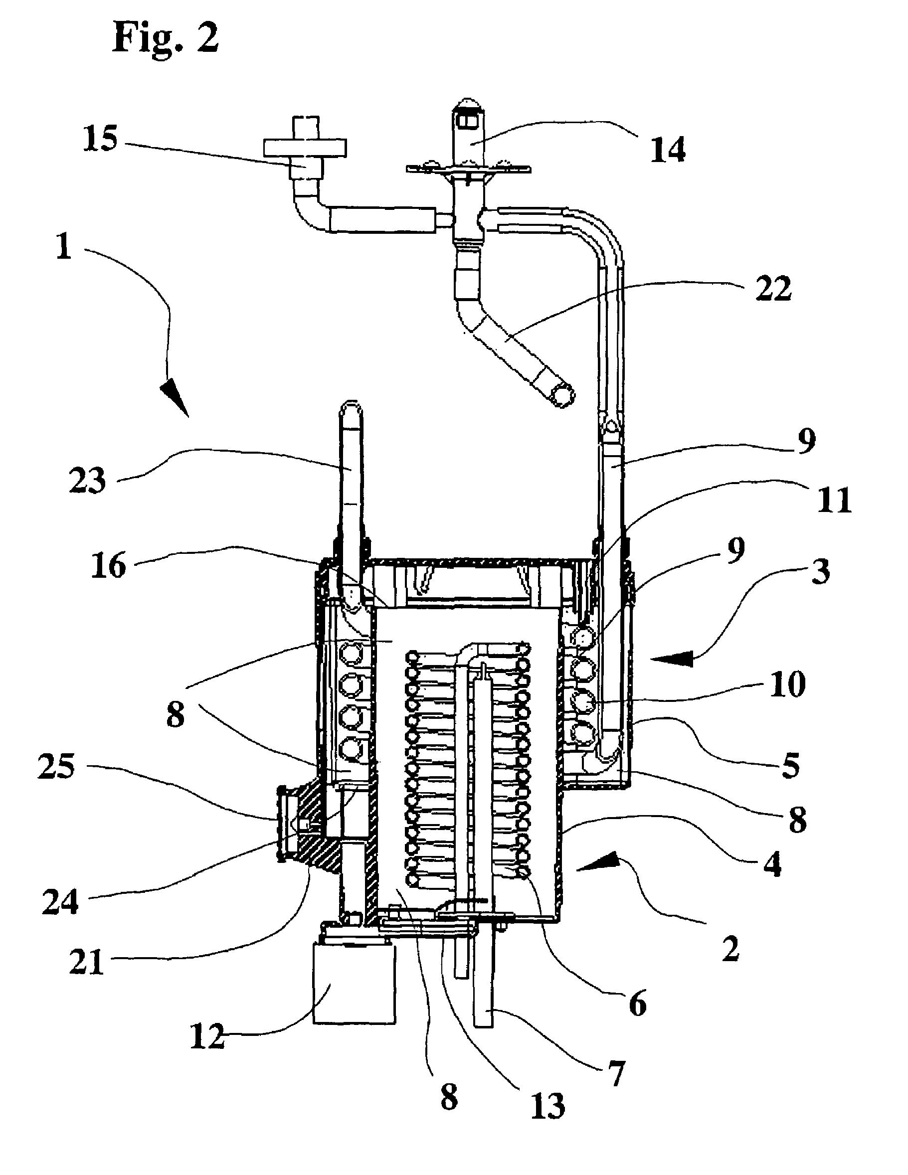
[0039]The fluid cooling system, indicated generally by reference 1, is a machine based on an ice bank system. The system 1 comprises a primary heat exchanger system, identified generally by the reference 2, and a secondary heat exchanger system, identified generally by the reference 3. The primary and secondary heat exchangers systems 2,3 each comprise a chamber 4,5 respectively. The chambers 4,5 are made of a plastic material. Chamber 4 of the primary heat exchanger system 2 houses an evaporator or coil 6 which is connected to a standard refrigeration system (not shown) outside of the primary 2 and secondary 3 heat exchanger systems. As can be seen from the FIGS. 1 and 2 chamber 4 is partly housed within chamber 5. The chambers 4 and 5 are preferably generally cylindrical in shape. The primary heat exchanger system 2 also comprises a thermostat 7, as defined previously, designed to regulate the temperature of heat transfer agent 8, in this case water contained inside chamber 4. In ...

example 2

[0045]The fluid cooling system, shown in FIGS. 3 and 4, and indicated generally by reference 101 comprises a primary heat exchanger, indicated generally by reference 102, a secondary heat exchanger indicated generally by reference 103, and a tank 118 that functions as a reservoir or storage tank to prime the pump 112 via tube 127 with heat exchange agent 108 and as a recovery unit for this same heat exchange agent 108.

[0046]The primary heat exchanger 102, in which cooling of the heat exchange agent occurs, comprises a tank or chamber 104, containing the heat exchange agent 108 that can be in either the fluid or solid phase around a coil (not shown), or a finger or other equivalent means known to the skilled person, but substantially as described for the preferred embodiment illustrated in FIGS. 1 and 2. The coil, in this case, is made of a suitable material that enables efficient energy transfer from the coil to the primary heat exchange agent, and is preferably made of metal, for e...


PUM


Abstract

The present invention relates to a fluid cooling system (1), for use in dispensing or distributing a chilled or cooled fluid, comprising a primary heat exchanger system (2), a secondary heat exchanger system (3), a first conduit (9) through which fluid to be cooled or chilled is circulated, and a heat transfer agent (8) for transferring cooling energy to the fluid to be chilled circulating in the first conduit (9), wherein the primary and secondary heat exchanger systems (2, 3) are arranged at least partially one inside of another The invention also relates to cooled fluid dispensers incorporating the fluid cooling system and a methods for sterilization thereof.

Description

FIELD OF THE INVENTION[0001]The present invention relates to fluid cooling systems and cooled fluid dispensers. In particular, the present invention will be described and explained in relation to cooled beverage dispensers, such as water dispensers, commonly used for dispensing cooled or chilled drinking water or other chilled beverages.BACKGROUND OF THE INVENTION[0002]Fluid cooling systems adapted for use in cooled fluid dispensers are generally known from applicant's prior published applications EP 1 129 024 and U.S. Pat. No. 6,442,960. In such systems, it is usual to find a primary heat exchanger system and a secondary heat exchanger system, with a heat transfer agent being cooled in the primary exchanger system. A conduit for fluid flow is also present through which circulates a fluid to be dispensed after cooling. Such cooling is effected by bringing the conduit containing the fluid to be dispensed into direct or indirect contact with the heat transfer agent that has previously...

Claims


Application Information

Patent Timeline
IPC IPC(8): F25D17/02A61L2/04B67D7/80A61L2/18B67D1/08F25B43/00F25D31/00
CPCA61L2/04A61L2/18F25D31/003F25B43/003B67D1/0864B67D2210/00013
Inventor DIETSCHI, ERICFOURNIER, ERICPEREIRA, ALEXANDRE
Owner DIEAUS
Why Eureka
Try Eureka