
RTD-HBT differential oscillator topology

a differential oscillator and differential oscillator technology, applied in pulse generators, pulse techniques, modulation, etc., can solve the problems of oscillator circuit, dc power consumption rtd, etc., and achieve low dc power consumption, increase negative conductance, and high cutoff frequency

Inactive Publication Date: 2009-08-11
KOREA ADVANCED INST OF SCI & TECH
View PDF4 Cites 0 Cited by
  • Summary
  • Abstract
  • Description
  • Claims
  • Application Information

AI Technical Summary

Benefits of technology

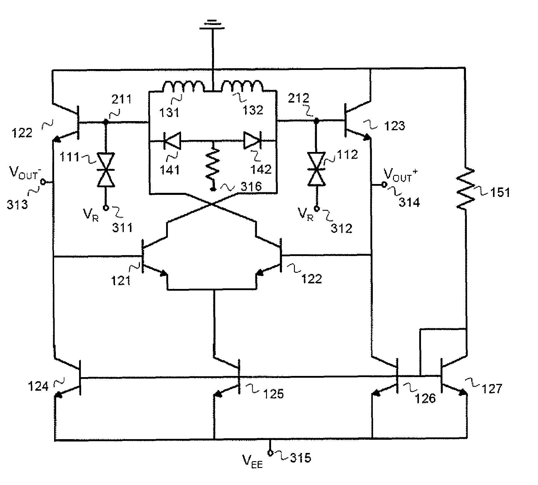
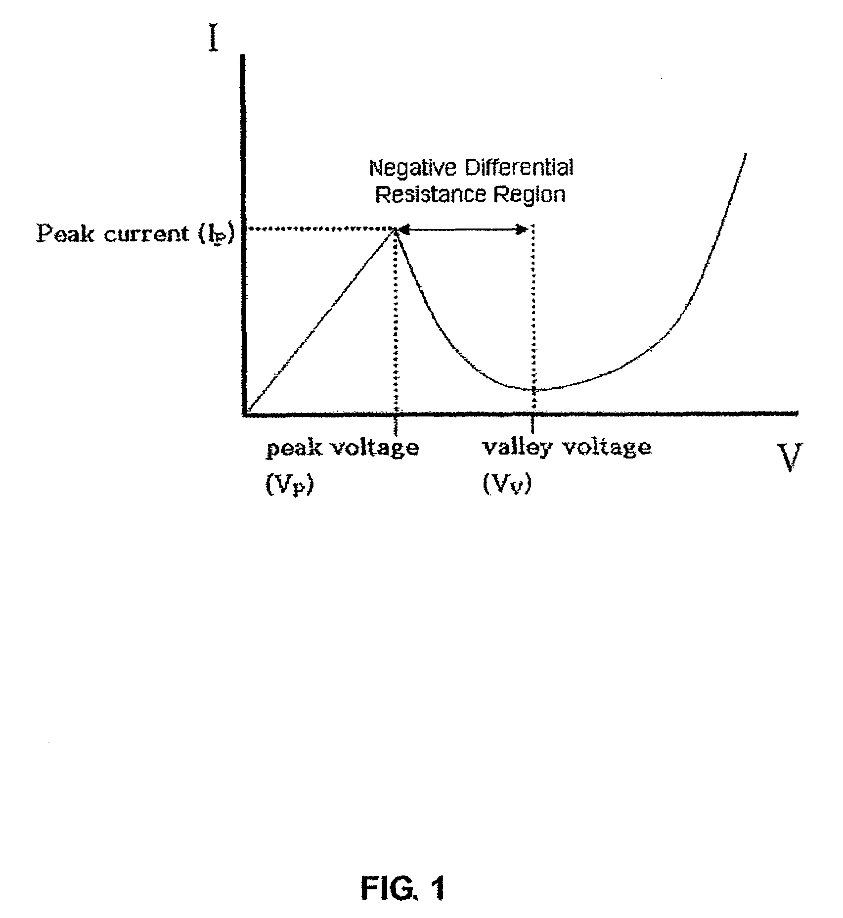
"The present invention provides a differential and enhanced RF power oscillator circuit for wireless communication systems. The circuit uses a InP based resonant tunneling Diode (RTD) and a Heterojunction bipolar transistor (HBT) for the tunnel and emitter, respectively. The RTD has high cutoff frequency, low DC power consumption, and room temperature operation, while the HBT has high efficiency and low DC power consumption. The circuit topology proposes the attachment of RTD to increase the negative conductance and improve RF output power and phase noise performance. The circuit generates differential sinusoidal waveforms and has similar DC power consumption to conventional HBT differential oscillators."

Problems solved by technology

In addition, the DC power consumption RTD-HBT differential oscillator circuit is similar to the conventional HBT differential oscillator due to the small DC power consumption performance of the RTD.

Method used


Image

  • RTD-HBT differential oscillator topology
  • RTD-HBT differential oscillator topology
  • RTD-HBT differential oscillator topology

Examples


Embodiment Construction

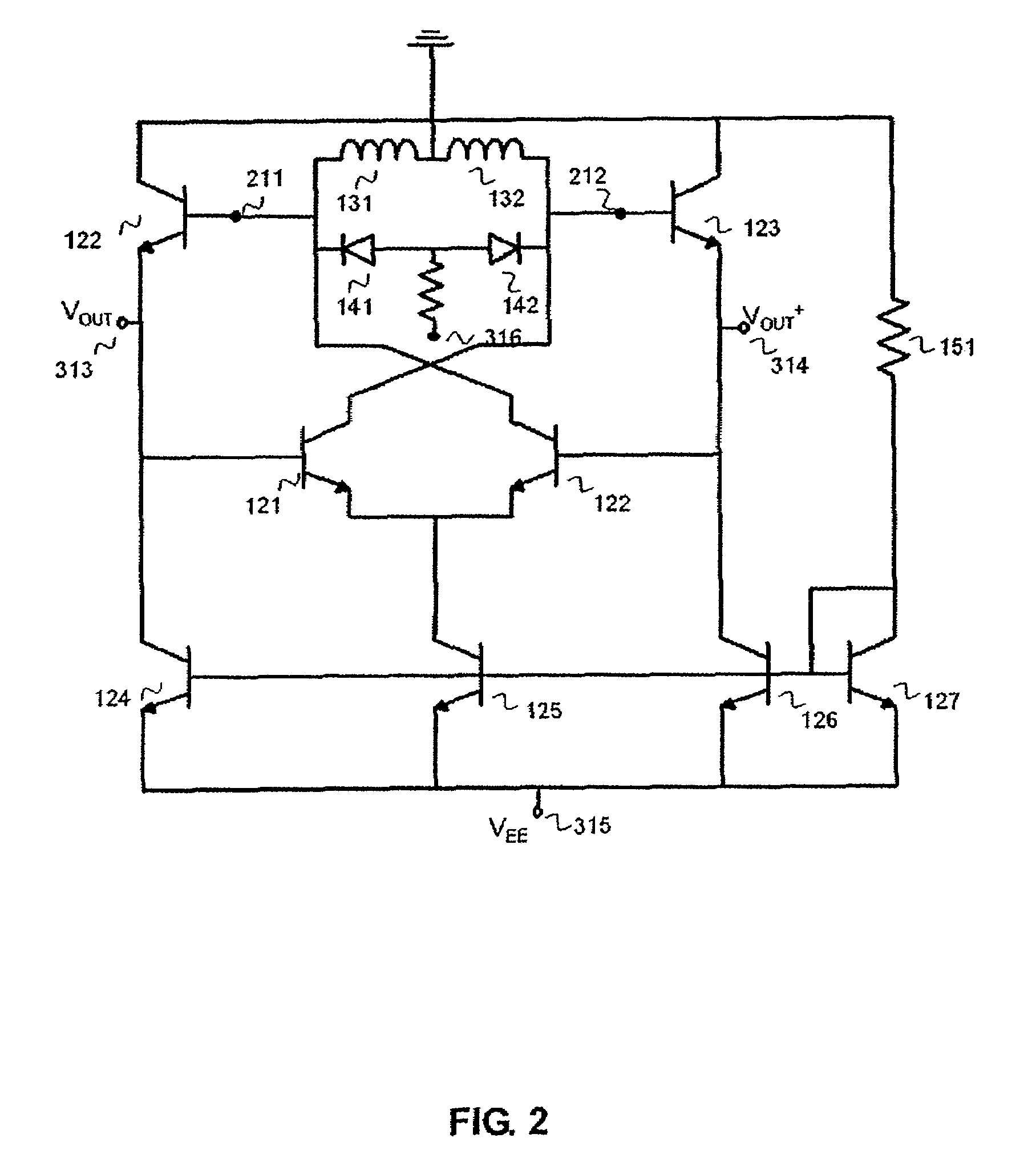
[0019]The present invention describes a differential and high RF power HBT / RTD oscillator circuit topology which is suitable for wireless communication system. FIG. 2. shows the conventional differential cross-coupled VCO topology by using the HBT. As shown in FIG. 2, the collector port of the HBT (121) is connected to the base of the HBT (123) which is operated as the buffer, and the emitter of the HBT (123) is connected to the base of the HBT (120). The collector port of the HBT (120) is connected to the base of the HBT (122) which is operated as the buffer, and the emitter of the HBT (122) is connected to the base of the HBT (121). In this cross-coupled topology, the negative conductance or negative resistance are shown in the node 211 and node 212. And the current mirror is consisted of the HBTs 124, 125, 126, and 127. The current mirror provides the current for the cross-coupled oscillator core.

[0020]The negative supply voltage is applied at the node 315. The oscillation freque...


PUM


Abstract

The new RTD-HBT differential oscillator circuit topology is proposed. At the nodes of the inductors and varactors in the conventional differential oscillator topology, each the RTD is attached to increase the magnitude of the negative conductance, which results in performance improvement in both the RF output power and phase noise. And, the differential sinusoidal voltage waveform which is essential for the wireless communication system are generated. In addition, the DC power consumption RTD-HBT differential oscillator circuit is similar to the conventional HBT differential oscillator due to the small DC power consumption performance of the RTD.

Description

BACKGROUND OF THE INVENTION[0001]1. Field of the Invention[0002]The present invention relates to Microwave / mm-wave band MMIC oscillator. More specifically, the present invention relates to the method to a high RF power and differential RTD-HBT oscillator which is a key element for wireless communication systems.[0003]2. Description of the Related Art[0004]Recently, the demand of the microwave and millimeter-wave wireless communication systems including the application areas of satellite communication, wireless LAN and local multipoint distribution services (LMDS) has been greatly increased. In these systems, a voltage controlled oscillator (VCO) is a crucial circuit block, which is used as a local oscillator or up and down converters. For the VCOs, one of the important performance requirements is low power consumption.[0005]In order to achieve the microwave signal generation at low power, the development of the negative cell, which operates at low bias voltage and current, is essent...

Claims


Application Information

Patent Timeline
Patent Type & Authority Patents(United States)
IPC IPC(8): H03B7/14H03K3/315
CPCH01L27/0605H01L29/7371H01L29/882H01L29/93H03B5/1221H03B5/1231H03B5/1215H03B5/1243H03B7/08H03B5/08H03B5/12
Inventor YANG, KYOUNG-HOONCHOI, SUN-KYUJEONG, YONGSIK
Owner KOREA ADVANCED INST OF SCI & TECH
Learn More