Temperature sensor and extensometer

a temperature sensor and extensometer technology, applied in the direction of speed/acceleration/shock measurement devices, digital computer details, measurement using magnetic resonance, etc., can solve the problems of thermal breakdown or aging of the electrically insulating medium surrounding the conductor, unsatisfactory physical sag, and failure of the dielectric insulation of the wire, etc., to achieve the effect of low power

Inactive Publication Date: 2009-08-18
FIELDMETRICS
View PDF20 Cites 22 Cited by
  • Summary
  • Abstract
  • Description
  • Claims
  • Application Information

AI Technical Summary

Benefits of technology

[0020]One advantage of the present invention is that the temperature is measured within the interior of the conductor, rather than at the surface of the conductor.
[0021]Another advantage of the present invention is that the conductor length can be measured using the same apparatus.
[0022]Another advantage of the present invention is that the sag of an overhead power line conductor can be calculated based on the measured conductor length.
[0023]Another advantage of the present invention is that it can be retrofitted to installed overhead power lines, transformer windings and underground coaxial power cables.
[0024]Another advantage of the present invention is that it requires low power to operate.
[0025]Another advantage of the present invention is that it is lightweight compared with other solutions.

Problems solved by technology

The thermal expansion of the conductor causes the conductor length to increase, resulting in undesirable physical sag when it is supported on its two ends by towers or poles.
The localized heating can lead to failure of the dielectric insulation on the wire.
In power transformers and underground or undersea power cables, the temperature rise of the conductor can cause thermal breakdown or aging of the electrically insulating medium surrounding the conductor.
Measuring the temperature of the conductor windings inside a power transformer is a difficult problem.
These methods also suffer from high cost, difficulty in retrofitting to installed equipment, or difficulty in generating accurate models of installed equipment for calculation purposes due to changes in material properties over time (for example, the emissivity of an overhead conductor changes with weather conditions and age, resulting in large errors in temperature measurements collected using thermal imaging).

Method used


Image

  • Temperature sensor and extensometer
  • Temperature sensor and extensometer
  • Temperature sensor and extensometer

Examples


Embodiment Construction

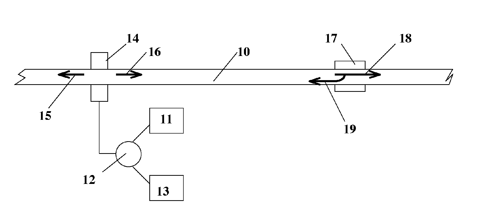
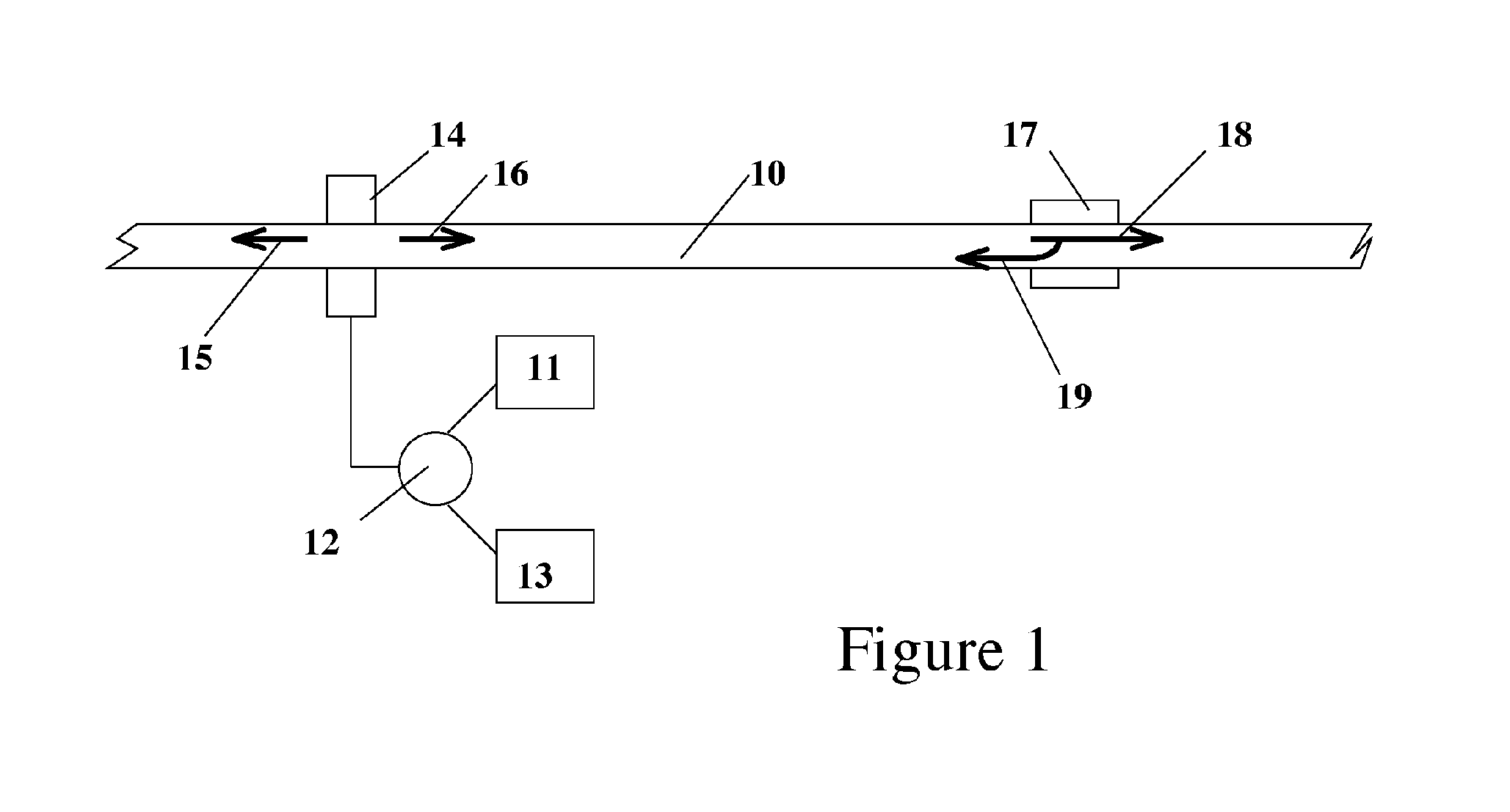
[0036]A thin cylindrical rod can support longitudinal (extension or bar) and transverse (torsional or shear) acoustic modes, along with a multitude of surface modes and combinations of modes. By controlling launch conditions and frequency content of the excitation, a subset of these modes can be excited. The launch conditions, rod diameter and acoustic frequency all depend on the cable dimensions and the properties of the cable materials. For the present application, longitudinal or torsional waves are of primary interest. Such waves will propagate in both the core and sheath of a conductor. The solution of the wave equation for the cylindrical bar is quite tedious and is not presented here for the sake of brevity, but the results are directly analogous to those for both electromagnetic and fiber optic waveguides. The critical aspects of the solution are the cutoff frequency and velocity dispersion behavior for various possible modes. This data is typically presented in terms of pha...


PUM

PropertyMeasurementUnit
lengthaaaaaaaaaa
relaxation frequencyaaaaaaaaaa
acoustic frequencyaaaaaaaaaa

Abstract

A thermometer and extensometer for cables and conductors is described. The travel time of one or more acoustic signals along a conductor is used to determine the temperature along the conductor and the length of the conductor. The acoustic frequency is selected to minimize temporal dispersion of the propagating acoustic energy. The technique can be used to measure the temperature and sag of an overhead power line, the temperature of the windings in a transformer, or the temperature of the central conductor in a coaxial power cable.

Description

CROSS REFERENCE TO PRIOR APPLICATION[0001]This application claims the priority of U.S. Provisional Application Ser. No. 60 / 522,833 filed Nov. 11, 2004 and entitled “Temperature Sensor and Extensometer”, the subject matter of which is incorporated herein by reference.FIELD OF THE INVENTION[0002]The present invention relates to measuring the temperature of a long conductor, to measuring the change in length of a long conductor, and to measuring the sag of an overhead power line conductor.DESCRIPTION OF THE PRIOR ART[0003]Often it is desirable to measure the temperature of an internal region of a long, cylindrical object. For example, electrically conductive wires used in power transmission and distribution systems operate at high temperatures when carrying large currents. Examples of these cables include stranded copper, all-aluminum (AAC), steel-reinforced aluminum (ACSR), and steel-supported aluminum (ACSS). The thermal expansion of the conductor causes the conductor length to incre...

Claims


Application Information

Patent Timeline
Patent Type & Authority Patents(United States)
IPC IPC(8): G01K11/24G01B17/00G01H5/00G01N29/00G01S15/00G01V1/00
CPCG01B17/04G01K11/24G01N29/07G01N29/4454G01N29/348G01K2217/00G01N2291/0421G01N2291/02854G01N2291/042
Inventor YAKYMYSHYN, CHRISTOPHER PAULBRUBAKER, MICHAEL ALLENHAMILTON, PAMELA JANE
Owner FIELDMETRICS
Why Eureka
Try Eureka