
Mechanical packaging of surface acoustic wave device for sensing applications

a surface acoustic wave and acoustic wave technology, applied in the field of acoustic wave devices, can solve the problems of faulty readings, low yield strength, and generally relatively complex devices, and achieve high yield strength, high glass transition temperature, and high young's modulus

Inactive Publication Date: 2009-08-18
HONEYWELL INT INC
View PDF13 Cites 8 Cited by
  • Summary
  • Abstract
  • Description
  • Claims
  • Application Information

AI Technical Summary

Benefits of technology

The use of a rigid bond adhesive eliminates sensor drift and enhances the reliability of tire pressure monitoring systems by reducing stress effects and maintaining accurate readings over time, while eliminating the need for batteries and their environmental impact.

Problems solved by technology

Such devices are generally relatively complex and expensive or alternatively are not particularly robust.
This system provides an indication of low tire pressure, but is also not very robust.
For example mud or other debris on the wheels may cause faulty readings.
Clearly such a system simply cannot provide a reading of actual tire pressure.
The batteries have a limited lifespan and suffer from impaired performance under the temperature conditions often experienced by automotive components, thereby reducing the reliability of such systems.
In addition, batteries contain chemicals that can have an adverse impact on the environment.
Further, the weight of the battery itself can cause distortion of tire shape at high speeds, causing loss of air pressure and resultant safety problems.
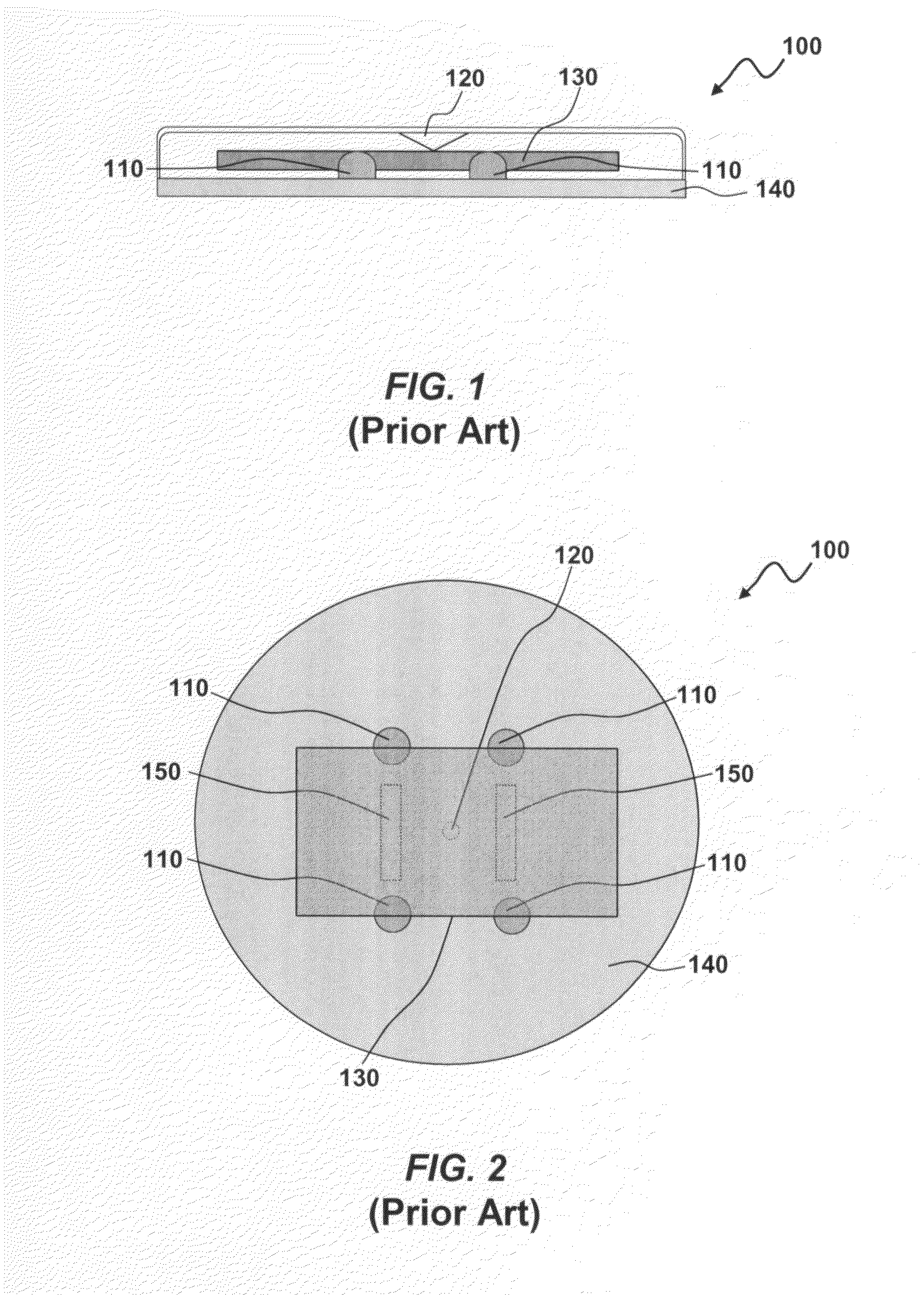
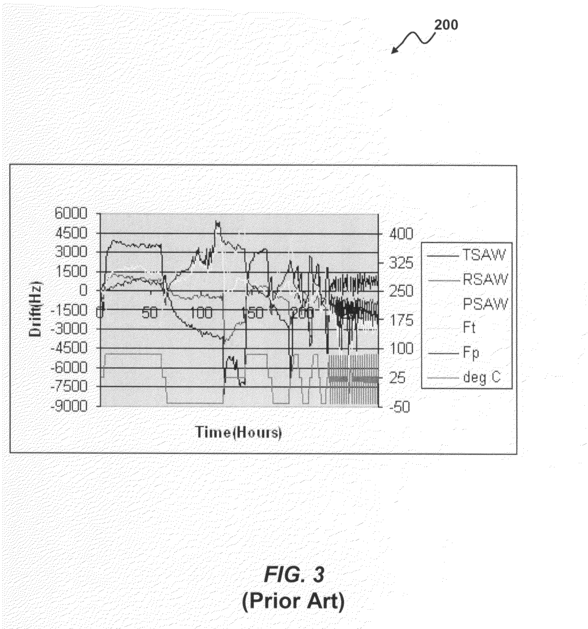
These issues can result in sensor drift over a period of time at different temperatures resulting in inaccurate and unreliable operations for a given sensing application.
The SAW sensor 100 is sensitive to these stress changes, resulting in an output drift from the sensor 100 and poor data.
Such a configuration causes the sensor 100 to drift over a period of time resulting in inaccurate and unreliable sensing operations and results.

Method used


Image

  • Mechanical packaging of surface acoustic wave device for sensing applications
  • Mechanical packaging of surface acoustic wave device for sensing applications
  • Mechanical packaging of surface acoustic wave device for sensing applications

Examples


Embodiment Construction

[0029]The particular values and configurations discussed in these non-limiting examples can be varied and are cited merely to illustrate at least one embodiment and are not intended to limit the scope thereof.

[0030]Referring to FIG. 4, a perspective view of an interdigital surface wave device 300 is illustrated, which can be implemented in accordance with a preferred embodiment. The surface wave device 300 depicted in FIG. 4 generally includes an interdigital transducer (IDT) 310 formed on a piezoelectric substrate 340. The surface wave device 300 can be implemented in the context of a sensor chip. The interdigital transducer 310 can be configured in the form of an electrode. The antenna 320 is generally connected to IDT 310.

[0031]A coating 330 can be utilized such that a particular species to be measured is absorbed by the coating 330, thereby altering the acoustic properties of the interdigital surface wave device 300. Various selective coatings can be utilized to implement the co...


PUM

PropertyMeasurementUnit
frequencyaaaaaaaaaa
temperatureaaaaaaaaaa
pressure effectaaaaaaaaaa

Abstract

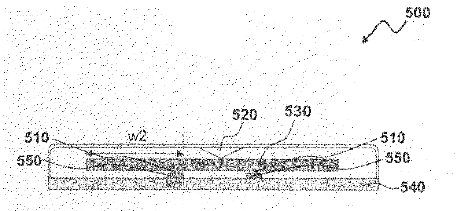
A method and apparatus, wherein a die is attached to a supporting base structure utilizing a rigid bond adhesive for a SAW (Surface Acoustic Wave) sensor. A rigid bond adhesive with a preferably high glass transition temperature (Tg) can be applied directly between the die and the die supporting structure in a pattern to eliminate time dependent gradual stress effects upon SAW sensor. The rigid bond adhesive can then be cured, which results in a high yield strength and a high young's modulus. The supporting base and the die material comprise a same co-efficient of thermal expansion in order to avoid die displacement over temperature.

Description

TECHNICAL FIELD[0001]Embodiments are generally related to acoustic wave devices. Embodiments are also related to SAW (Surface Acoustic Wave) and BAW (Bulk Acoustic Wave) sensing devices. Embodiments are additionally related to mechanical packaging techniques and configurations for surface acoustic wave sensor devices.BACKGROUND OF THE INVENTION[0002]Acoustic wave sensors such as, for example SAW and / or BAW based sensors, can be utilized in a variety of sensing applications, such as, temperature and / or pressure sensing. Such surface wave sensors can also be utilized to detect the presence of substances, such as chemicals. Surface acoustic wave devices are typically fabricated using photolithographic techniques with comb-like interdigital transducers placed on a piezoelectric material. Surface acoustic wave devices may have either a delay line or a resonator configuration. One application where SAW sensors have been utilized effectively involves pressure and / or temperature sensing of ...

Claims


Application Information

Patent Timeline
Patent Type & Authority Patents(United States)
IPC IPC(8): H01L41/08H10N30/00H10N30/01
CPCG01L9/0025Y10T29/42G01L9/00H03H9/25
Inventor KUMAR, SACHINCOOK, JAMES D.O'BRIEN, GARYQASIMI, MOHAMMED A JSORENSON, RICHARD C.MARSH, BRIAN J.AVRAMESCU, VIOREL V.
Owner HONEYWELL INT INC
Learn More