Apparatus and method for determining patterns of damage being caused in rolling contact element

a technology of rolling contact element and pattern, applied in the direction of apparatus for force/torque/work measurement, instruments, analogue processes for specific applications, etc., can solve the problems of bearing damage, pitching or flaking, and no definite solution obtained to clarify, so as to avoid bearing damage

Inactive Publication Date: 2009-08-18
DENSO CORP
View PDF12 Cites 4 Cited by
  • Summary
  • Abstract
  • Description
  • Claims
  • Application Information

AI Technical Summary

Benefits of technology

[0016]The present invention has been completed with a view to addressing the above issues and has an object to provide a method of designing a roller bearing to be of assistance in preventing the bearing from mechanical damage by providing capabilities of clarifying factors of all damage patterns in a primary failure caused in the roller bearing and preventing the roller bearing from damage and enabling judgment of all the damage patterns using a size of one physical quantity (ex stress, load etc.) to make it possible for everybody to make design of the bearing in a simplified fashion with no error.

Problems solved by technology

Despite the bearing playing a role as an important component part, there are many probabilities in which no definite solution is obtained to clarify what is to be made to avoid such damages.
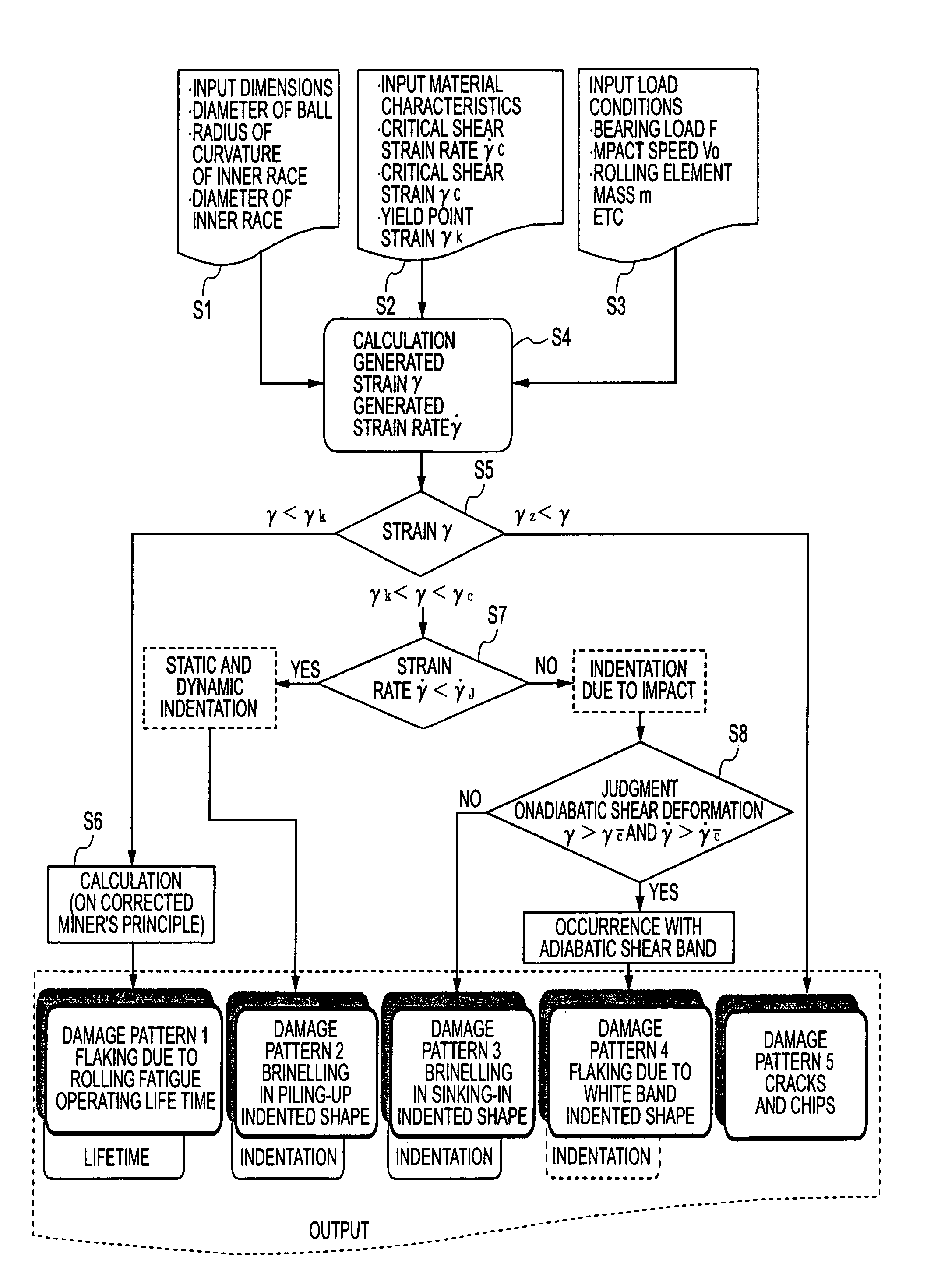
That is, with a consequence of the fatigue life, a final damage pattern results in pitching or flaking.
Moreover, when experienced with permanent deformation, the damage pattern results in brinelling (in a brinelling indentation).
Despite such brinelling, the bearing suffers from, in addition to such a damage pattern, other damages in various patterns.
All of the causes for these phenomena are clarified but no distinct solution is provided for which of a threshold value of the cause results in the occurrence of damage to the bearing.
Therefore at the current status quo, it is quite difficult to make a design of a bearing in a preliminary stage to avoid such phenomenon.
This results in exposure of flaking accompanied by variation in tissue under new patterns.
To be different from a consequence in which all of roller bearings, subjected to rolling life tests conducted on flaking based on a fatigue in the related art practice, are caused to suffer from fatigue breakdown on a final stage, no mechanism of such brittle flaking has been determined yet.
That is, this theory stands on the ground that a ball is caused to slip due to stress such as vibrations applied to the bearing in use and heat and pressure develop in the bearing to cause the decomposition of grease into hydrogen with the resultant occurrence of flaking due to hydrogen brittleness.
However, as a result of various tests conducted by the present inventors, these attempts have not always been successful in the prevention of flaking.
Certainly, a bearing made of steel forcedly added with hydrogen in a preceding step undergoes white-banded flaking within a short time interval during a test in most of the conditions but no conclusion was obtained in the bearing wherein grease is decomposed into hydrogen during normal operation to cause hydrogen to penetrate into steel resulting in white-banded flaking due to hydrogen brittleness.
As set forth above, none of the mechanisms meets actual conditions for brittle flaking to take place in new types of damage patterns and it is completely unclear to determine which of stress factors of a real machine adversely affects on the occurrence of flaking.
With such a structure, an issue progressively arises in an increase in belt tension, belt resonance and promoted engine vibration or the like and under such conditions bearings suffer from stress in a complicated pattern.
None of the theories, proposed in the past as mentioned above, have made solutions to the occurrence of such brittle flaking.
In spite of the roller bearing playing a role as the important mechanical element component part, not only full-fledged measure had not be taken to address the issue of brittle flaking but also even the mechanism for addressing such issue had not been established.
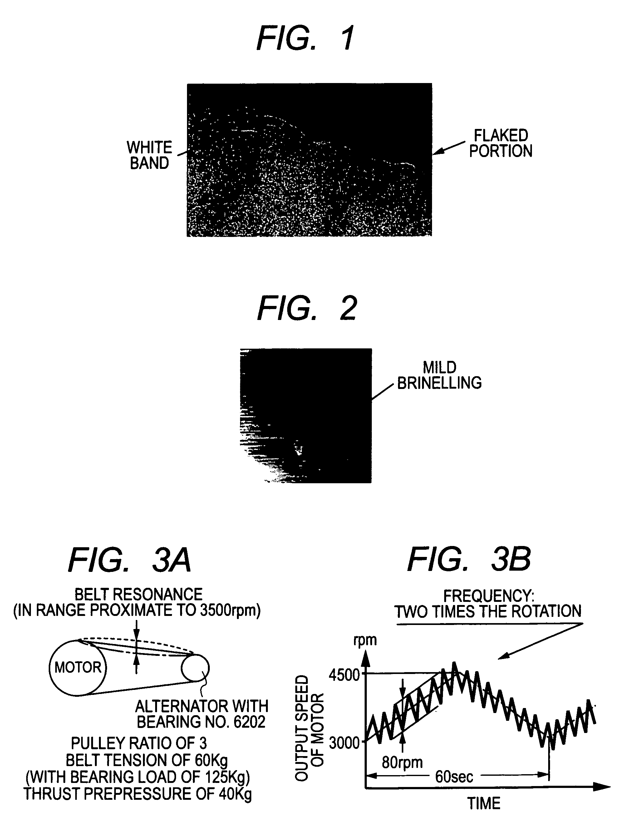
Further, certain damage with mild brinelling has come to be found in a bearing installed on an alternator employing a modern serpentine drive system (see FIG. 2).
Among bearings subjected to mild brinelling, some bearings have come out to consequences wherein due to adversely affect resulting from such mild brinelling, balls of the bearings tend to be worn each in a band-like configuration to evolve into a pattern liable to be mistaken to be grinding burn.
Although there is a common idea in that the bearing is subjected to vibration accompanied by an indentation during a transportation of an automobile on a ship or a trailer, no way exists for mild wear to take place because damage of this kind has not been recognized in bearings of the related art belt drive system prior to the employment of a serpentine drive system and even during a halt of an engine, belt tension has prevented the bearings from being subjected to undulation resulting from vibrations caused during transportation.
If the primary failure (in the form of mild brinelling) can be suppressed, then, no various secondary failures induced from such a primary failure take place and, therefore, a need arises to suppress the occurrence of mild brinelling but even such a mechanism has not been established in the related art.
Further, in spite of an extremely short operating life resulting from brittle flaking caused in a modern bearing as compared to that of a commonly experienced fatigue life (no problems had arisen in alternators in actual practice), no mechanism for explaining such a phenomenon has been established and a situation stands with no capability of taking appropriate measure to address the issue.
With no alternatives, woefully inefficient methods in irregular measures have heretofore been taken in this status quo for each of the auxiliary units of the engines upon conducting a test of the bearing on a real machine for confirmation.
This results in wasteful efforts involving a step of manufacturing a bearing with an unnecessary increase in size or a bearing with increased prevision.
Even with such attempts, such an inconvenience could not be completely addressed.
Also, no mechanism for the occurrence of mild brinelling in a modern bearing had been clarified in the status quo.

Method used


Image

  • Apparatus and method for determining patterns of damage being caused in rolling contact element
  • Apparatus and method for determining patterns of damage being caused in rolling contact element
  • Apparatus and method for determining patterns of damage being caused in rolling contact element

Examples


Embodiment Construction

[0079]An embodiment of the present invention will now be described, together with a further description of the mechanism of brittle flaking.

[0080]At first, a further detailed mechanism of brittle flaking is described below.

[0081][1] First, description is made of white-banded flaking (brittle flaking) forming a damage pattern like that shown in FIG. 1.

[0082]As set forth above, the present inventors have come to the conclusion that the white band constitutes a so-called “adiabatic shear deformation band”.

[0083]The adiabatic shear deformation band is observed as a white band in high strength steel. This adiabatic shear deformation band is regarded to be a plastic instability phenomenon that appears under high-velocity deformation. According to Stake's study, this theory stands on the ground that as shear strain and a strain rate inside a bearing exceed material-specific threshold limit values (γc, γ c), a white band occurs with the resultant occurrence of cracking and flaking. These va...


PUM


Abstract

A method of designing a roller bearing is disclosed upon clarifying mechanisms of damage patterns in respect of two kinds of brinelling, involved in the bearing, wherein white-banded flaking (brittle flaking) is a plastic instability phenomenon appearing under high-speed deformation accompanied by adiabatic shear deformation status with the resultant occurrence of adiabatic shear band (also called white band) inside material of the bearing. This enables all of the damage patterns to be determined upon making comparison between shear strain and shear strain rate, occurring inside the bearing, and discriminated values.

Description

CROSS REFERENCE TO RELATED APPLICATIONS[0001]This application is related to Japanese Patent Application No. 2005-215378 filed on Jul. 26, 2005, the content of which is hereby incorporated by reference.BACKGROUND OF THE INVENTION[0002]1. Technical Field of the Invention[0003]The present invention relates to an apparatus and method for determining patterns of damage being caused in a rolling contact element such as rolling bearings including a roller baring, and in particular, to a design technique for clarifying the relationship between a damage pattern in a contact area of the rolling contact element and stress to avoid the rolling contact element from abnormal damage.[0004]2. Description of the Related Art[0005]A rolling element, playing a role as a mechanical element, that is, among others, a roller bearing in common use suffers from damages in various patterns. Despite the bearing playing a role as an important component part, there are many probabilities in which no definite sol...

Claims


Application Information

Patent Timeline
Patent Type & Authority Patents(United States)
IPC IPC(8): G06F17/10
CPCF16C19/00G01M13/04G06F17/50G01N2203/006G01N2203/0226G01N2203/0218Y02T10/82G01N2203/0222G01N2203/0039G01N2203/0212G01N2203/0098G01N2203/0067G01N2203/0228G06F30/00
Inventor UMEDA, ATSUSHISHIGA, TSUTOMUIHATA, KOUICHI
Owner DENSO CORP
Why Eureka
Try Eureka