High-efficiency parallel-pole molded-magnetic flux channels transverse wound motor-dynamo

a technology of parallel-pole molded magnets and flux channels, applied in the direction of dynamo-electric machines, magnetic circuit shapes/forms/construction, electrical apparatus, etc., can solve the problems of reducing the maximum torque produced, reducing the magnetic strength, and only blocking the eddy current in one plan

Inactive Publication Date: 2009-08-25
RITTENHOUSE NORMAN
View PDF19 Cites 92 Cited by
  • Summary
  • Abstract
  • Description
  • Claims
  • Application Information

AI Technical Summary

Benefits of technology

[0011]A secondary objective of the invention is to provide apparatus, methods, systems, and devices for a high efficiency direct drive high torque motor constructed using Parallel Pole Molded Magnetic Flux Channels, which increases the overall efficiency by greatly reducing eddy currents in all planes.
[0021]A first preferred embodiment of the invention provides a motor comprised of a mounting shaft having a hollow channel and a bearing attached to each end of the mounting shaft, a non-rotating cylindrical hub having a hollow core for the mounting shaft, plural rows of plural Parallel Pole Molded Magnetic Flux Channels each, comprised of two halves, forming a hollow channel which conductive wire is transversely wound through. Each complete Parallel Pole Molded Magnetic Flux Channels fixedly attached on a cylindrical surface of the cylindrical hub. Each one of the plural rows corresponding to a phase of the motor, wherein each one of the plural magnetic flux channels forms two parallel pole pieces, North and South. Plural phase windings, one of the plural transverse windings passing through one of the rows of plural magnetic flux channels and corresponding to one phase, a rotating drum having plural paired rows of plural permanent magnets on an inner surface, each paired row corresponding to and aligned with one of the plural rows of molded magnetic flux channels, the rotating drum connected with the bearing to allow the plural rows of permanent magnets to rotate around the cylindrical hub, and drive electronics for driving the plural phase windings with variable timing advance and current pulse shaping, wherein the plural molded magnetic flux channels capture nearly all the available magnetic flux of the transverse winding which increases torque and motor efficiency.

Problems solved by technology

However, even with thinner laminations, the eddy currents are only blocked in one plane.
Although the silicon reduces some remaining eddy current losses (by reducing the current conductivity), the addition of silicon actually worsens the magnetic conductivity.
This reduction of magnetic strength reduces the maximum amount of torque produced, and also reduces electrical efficiency.
The close-coupled proximity results in “Armature Effect” which reduces efficiency at higher speeds.
At higher speeds, the inductive and reactive losses limit top speed and efficiency at high speed.
However, it does not involve Transverse Flux and does not use molded material for the stator.
Prior art transverse Flux motors have historically been too costly to construct, and have rarely been used.

Method used


Image

  • High-efficiency parallel-pole molded-magnetic flux channels transverse wound motor-dynamo
  • High-efficiency parallel-pole molded-magnetic flux channels transverse wound motor-dynamo
  • High-efficiency parallel-pole molded-magnetic flux channels transverse wound motor-dynamo

Examples


Embodiment Construction

[0045]Before explaining the disclosed embodiments of the present invention in detail it is to be understood that the invention is not limited in its application to the details of the particular arrangements shown since the invention is capable of other embodiments. Also, the terminology used herein is for the purpose of description and not of limitation.

[0046]The following is a list of the reference numbers used in the drawings and the detailed specification to identify components:

[0047]

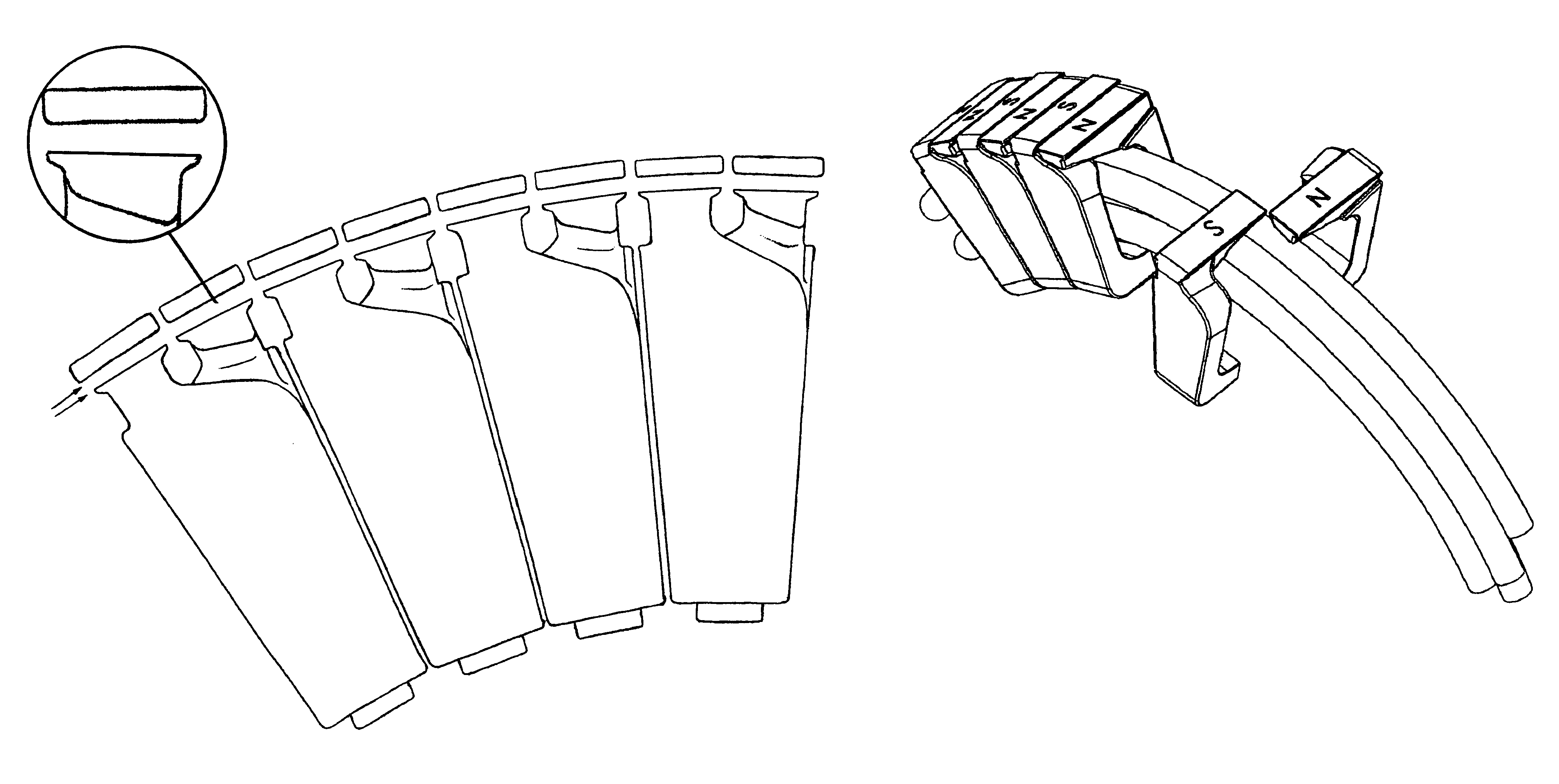
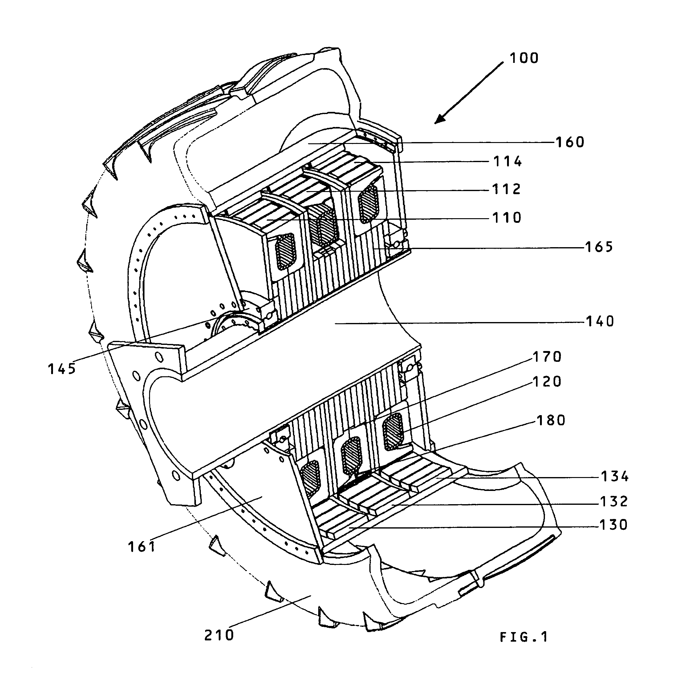
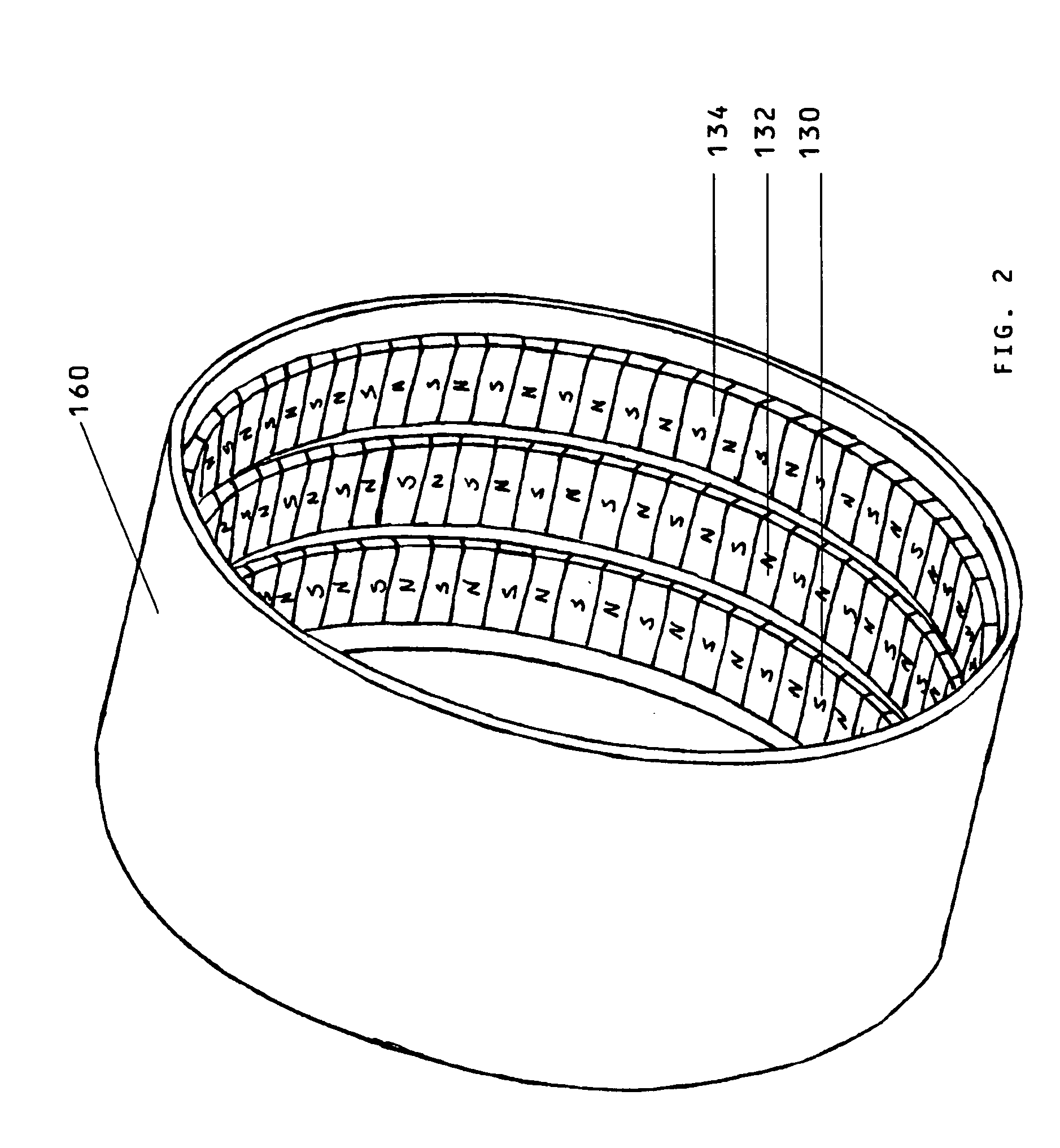
100motor110pole pieces, phase “A”112pole pieces, phase “B”114pole pieces, phase “C”120transverse wire winding130row of magnets, Phase “A”132row of magnets, Phase “B”134row of magnets, Phase “C”136epoxy140mounting shaft145bearing150Magnetic Flux Channels160magnetic drum outer shell161rotating side plate162mounting shaft hole165hub170locating key172north parallel pole piece174south parallel pole piece175hollow core177gap180air gap200wheel motor210tire220location ridge222machined axial flat224epoxy powd...


PUM


Abstract

A motor / dynamo including a mounting shaft having a hollow channel and a bearing attached to each end, a non-rotating cylindrical hub having a hollow core for the mounting shaft, single or plural rows of plural parallel pole molded magnetic flux channels each having two halves and forming a hollow channel through which wire is transversely wound through fixedly attached on a surface of the cylindrical hub forming a high efficiency, high torque, direct drive motor / dynamo, utilizing Parallel Pole Molded Magnetic Flux Channels, low resistance and impedance transverse coil windings, and physically separate stators for electrical phases. The high torque, high efficiency motor capable of driving wheels, tracks, propellers, and other loads without a gearbox or other torque multiplying device. The high efficiency dynamo capable of being directly driven by wind turbines without a speed increasing gearbox or other speed multiplying device.

Description

FIELD OF THE INVENTION[0001]This invention relates to motors and, in particular, to methods, systems, apparatus, and devices for a high efficiency direct drive high torque motor utilizing parallel pole molded magnetic flux channels with transverse flux stator windings, and separate stators for each phase.BACKGROUND AND PRIOR ART[0002]Approximately 93% of motors constructed use iron cores, or variations thereof, to concentrate magnetic flux and boost torque. “Coreless” motors are suited for very high RPM's with low torque and iron core motors usually utilize insulated steel laminations in their stators, which reduce heat losses from eddy currents. However, even with thinner laminations, the eddy currents are only blocked in one plane. So to further reduce eddy current losses, silicon is typically added to the steel to reduce its electrical conductivity. Although the silicon reduces some remaining eddy current losses (by reducing the current conductivity), the addition of silicon actu...

Claims


Application Information

Patent Timeline
Patent Type & Authority Patents(United States)
IPC IPC(8): H02K1/12H02K21/12
CPCH02K1/141H02K1/2786H02K1/145H02K1/2791
Inventor RITTENHOUSE, NORMAN
Owner RITTENHOUSE NORMAN
Why Eureka
Try Eureka