

Magnetic element, magnetic information reproducing head, and magnetic information reproducing apparatus
a technology of magnetic information and reproducing head, which is applied in the field of magnetic information reproducing apparatus, and magnetic information reproducing head, which can solve the problems that magnetic white noise can pose a serious problem in high-density magnetic recording, and achieve enhanced magnetoresistance change, high recording density, and no reduction of sensitivity and signal-to-noise ratio.
- Summary
- Abstract
- Description
- Claims
- Application Information
AI Technical Summary
Benefits of technology
Problems solved by technology
Method used
Image

Examples
first embodiment
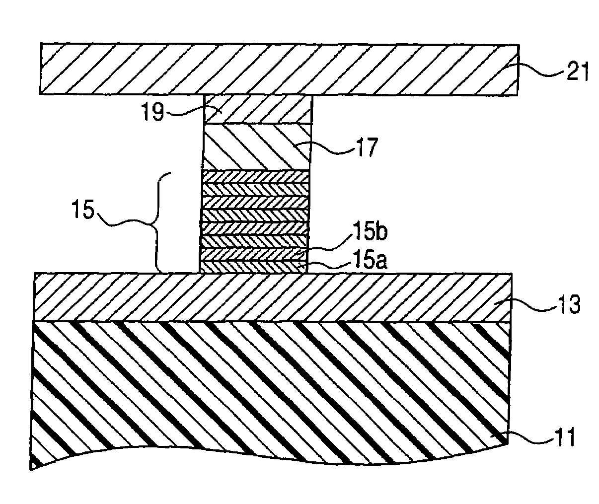
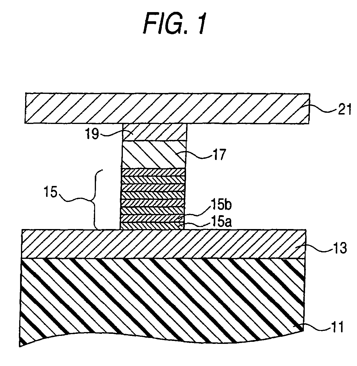
[0035]FIG. 1 is a sectional view for explaining a magnetic element according to a first embodiment of the invention.
[0036]The magnetic element is deposited on a substrate 11 in FIG. 1, and has a lower electrode 13 which also serves as a magnetic shield, an artificial lattice film (also called an “artificial antiferromagnetic film”) 15 which is deposited thereon, a nonmagnetic film 17, a ferromagnetic film 19, and an upper electrode 21 which also serves as a magnetic shield. The lower electrode 13 and the upper electrode 21, which also serve as wiring, extend laterally in the plane of FIG. 1, and are connected at their end portions to a current supply circuit which controls a current flow to the element, a reading (sense) circuit, or the like.
[0037]In the above embodiment, the lower electrode 13 and the upper electrode 21 serve as both a magnetic shield and wiring. However, a magnetic shield and wiring may be provided separately. Even in such a case, a magnetic shield and wiring can ...
second embodiment
[0107]The previous embodiment has examined a spin dependence of interface reflection in relation to an injection efficiency of transverse component of spins under injection from a nonmagnetic film 17 into a magnetic film (e.g., an artificial antimagnetic film 15).
[0108]As shown in FIG. 5, up-spins and down-spins have different band structures in the magnetic material 15. For this reason, the potential barrier of the interface depends on spins (a potential barrier of an up-spin is indicated by V↑, and that of a down-spin is indicated by V↓).
[0109]Now, the direction of a quantization axis (i.e., the direction of the internal magnetic field of the second magnetic material) and a spin function sloped at an angle θ can be represented as the following equation (17).
[0110]ψ=ⅇⅈkx(cosθ2,sinθ2)(17)
[0111]The equation (17) indicates that when energy of an electron entering from the nonmagnetic material 17 into the magnetic material falls within the range of V↑ to V↓, only an up-spin compon...
example 1
[0127]Example 1 of the invention will be described below by reference to FIG. 11, which shows a sectional schematic diagram.
[0128]In the present embodiment, thermal fluctuation of magnetization of a ferromagnetic material was measured first.
[0129]First, the following films were stacked on a silicon substrate 31 by means of sputtering operation and electron beam lithography. The multilayer film has a nonmagnetic Cu layer 33, a ferromagnetic Co layer 35, a nonmagnetic Cu layer 37, a ferromagnetic Fe layer 39, a nonmagnetic Cu layer 41, a nonmagnetic Au layer 43, and a nonmagnetic Cu layer 45 deposited on the substrate 31, in the order given.
[0130]Thicknesses of the respective layers are set as follows: namely, the Cu layer 33 assumes a thickness of about 100 nm; the Co layer 35 assumes a thickness of about 50 nm; the Cu layer 37 assumes a thickness of about 30 nm; the Fe layer assumes a thickness of about 1 nm; the Cu layer 41 assumes a thickness of about 10 nm; the Au layer assumes a...
PUM
| Property | Measurement | Unit |
|---|---|---|
| thickness | aaaaa | aaaaa |
| area | aaaaa | aaaaa |
| junction area | aaaaa | aaaaa |
Abstract
Description
Claims
Application Information