Anti-vibratory device with rotary compensation weights

a technology of anti-vibration device and compensation weight, which is applied in the direction of mechanical vibration separation, rotocraft, air-flow influencer, etc., can solve the problems of reduced changes frequency, limited effectiveness of devices of that type, and reduced effectiveness of anti-vibration devices, so as to reduce the dimensions and weight of the anti-vibration device

Active Publication Date: 2009-09-01
EUROCOPTER
View PDF7 Cites 16 Cited by
  • Summary
  • Abstract
  • Description
  • Claims
  • Application Information

AI Technical Summary

Benefits of technology

[0018]An object of the present invention is to remedy those drawbacks. Moreover, in order to be installed in a aircraft, such as a helicopter, the dimensions and the weight of the antivibration device shall be reduced.

Problems solved by technology

Nevertheless, their effectiveness is limited since they act only on vibration having the predetermined frequency, and not on vibration at other frequencies.
In addition, devices of that type become ineffective when the vibration that is to be reduced changes frequency.
Although giving advantageous results, that antivibration device presents a certain number of drawbacks such as heavy weight (about 10 kilograms (kg) for each resonator), which is always penalizing in the field of aviation, and high energy consumption if it is to be effective in treating the levels of vibration that are to be encountered in helicopters.
Thus, the rotation of each rotor produces a rotary unbalance and, since the rotors are both disposed in the same plane, they produce unbalance that is identical but turning in opposite directions.
This results in a sinusoidal force in the direction that is perpendicular to the plane containing the axes of rotation of the rotors, since the components of the unbalances within this plane are opposite and therefore cancel.
Although those antivibration devices having rotary unbalance weights provide considerable progress in treating vibration, they nevertheless present drawbacks, and in particular:an increase in the level of vibration (instead of a decrease) in the event of a breakdown.
Should the motors of the two modules cease to rotate at the same speed, for any reason whatsoever, the resulting vibratory force is no longer under control, thereby leading immediately to greatly degraded comfort, which becomes significantly worse than it would be in the absence of any treatment;a control unit that is quite complex since it needs to synchronize the modules while the motors are getting up to speed, thereby complicating the control algorithms and correspondingly increasing the risk of a breakdown; andrelatively high cost because of the large number of expensive components: several motors, sets of gearing, and a control unit that is complex since it is required to synchronize the speeds of the motors and servo-control their phase difference in order to implement an active system.

Method used


Image

  • Anti-vibratory device with rotary compensation weights
  • Anti-vibratory device with rotary compensation weights
  • Anti-vibratory device with rotary compensation weights

Examples


Embodiment Construction

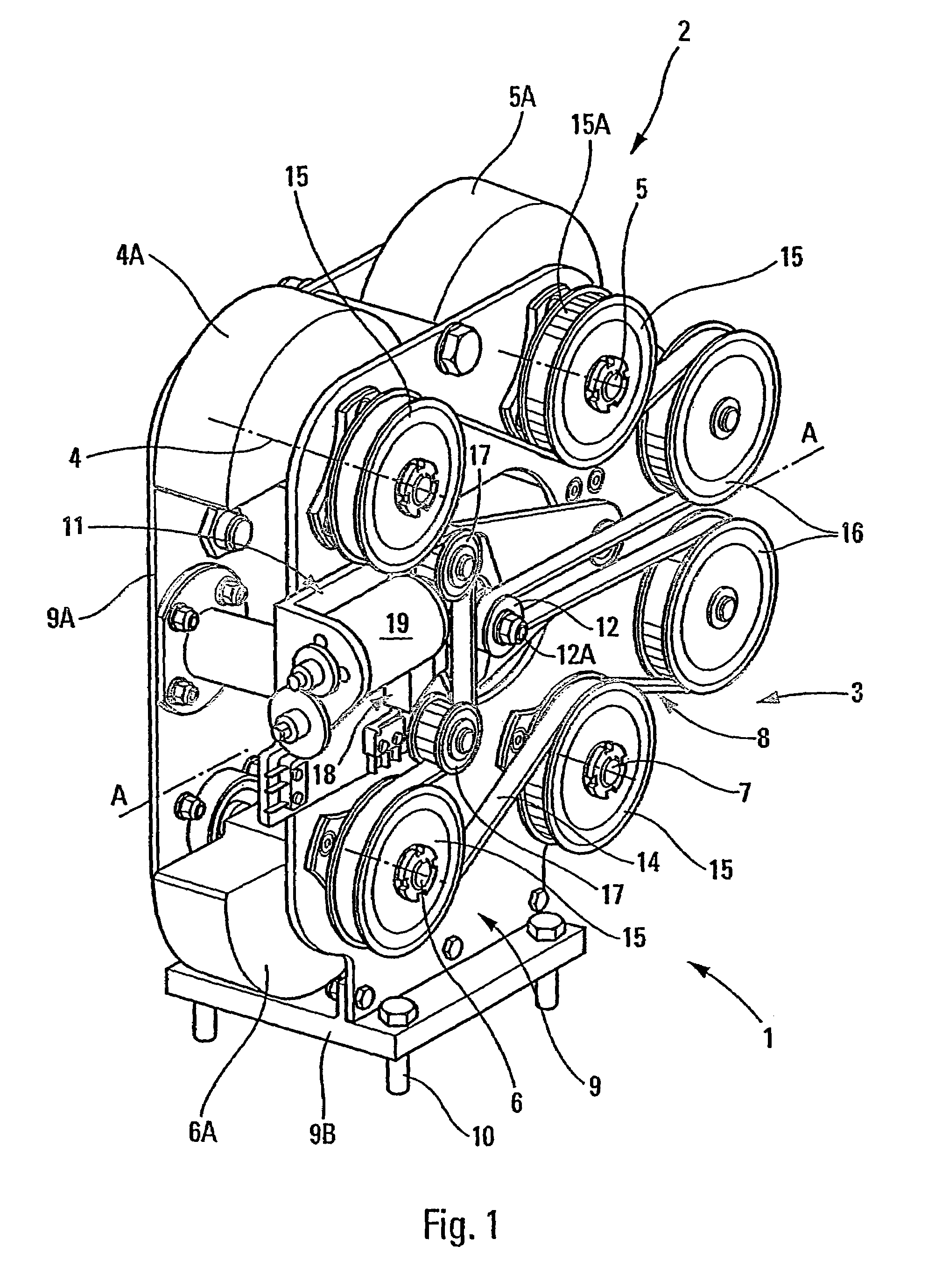
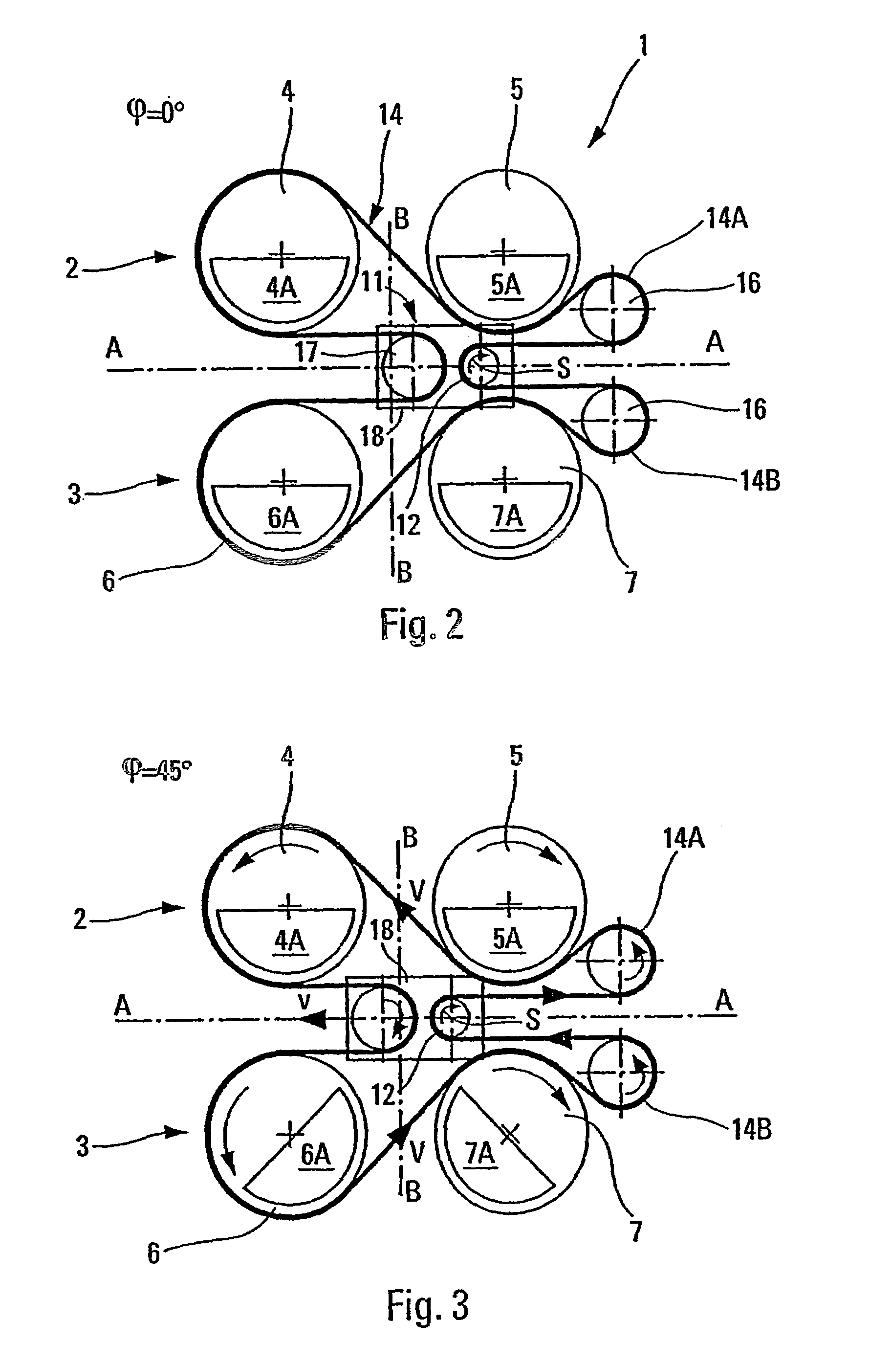
[0037]The antivibration device 1 shown in FIG. 1 comprises two identical modules or sets 2 and 3 each comprising two rotors or rotary shafts respectively referenced 4, 5 and 6, 7, and associated with respective flyweights 4A, 5A and 6A, 7A that are eccentric relative to the axes of rotation of the rotors. In this embodiment, the two sets 2, 3 are disposed in a common vertical plane and are separated from each other about an axis of symmetry A that is horizontal. The axes of the rotors 4, 5, 6, and 7 are parallel to one another (horizontal in this example) and orthogonal to the axis of symmetry A of the identical sets 2, 3 such that the rotors are opposite in pairs, the rotors 4, 5 and 6, 7 being at equal distances from an axis of symmetry B (vertical in FIGS. 2 to 6) that is orthogonal to the axis of symmetry A.

[0038]A drive system 8 serves to drive the rotors 4, 5, 6 and 7.

[0039]In addition, the rotors of said sets are carried, via bearings (not shown), by a frame 9 constituted by ...


PUM


Abstract

An anti-vibratory device with rotary compensation weights includes two sets of two identical rotors with respective eccentric compensation weights, the units being symmetrically disposed in relation to an axis of symmetry and the axes of rotation of the rotors being parallel between themselves and orthogonal in relation to the axis of symmetry; and a rotational drive system for the rotors. Advantageously, the device includes controllable mobile equipment carrying the drive system and being able to slide along the axis of symmetry in order to drive the dephasing of the rotors with eccentric compensation weights associated with the sets.

Description

BACKGROUND OF THE INVENTION[0001]1. Field of the Invention[0002]The present invention relates to an antivibration device.[0003]More particularly, although not exclusively, in its preferred application, the device of the invention is designed for mounting on board of aircraft, in particular in the cabin of a rotary wing aircraft such as a helicopter, but it could naturally be used for any other application where there is a desire to reduce or even eliminate vibration generated by a moving body.[0004]2. Description of the Related Art[0005]The problem of controlling vibration in a helicopter cabin is described in detail in the introduction of French patent No. 2 770 825 (U.S. Pat. No. 6,067,853). In short, the main existing vibration is due to rotation of the main rotor for providing lift and propulsion, and to the air flow along the helicopter fuselage.[0006]In an attempt to absorb this vibration that appears in the cabin, resonator antivibration devices have been proposed that act by...

Claims


Application Information

Patent Timeline
Patent Type & Authority Patents(United States)
IPC IPC(8): F16H7/20B06B1/16B64C27/00F16F15/22
CPCB06B1/166F16F15/22B64C27/001B64C2027/004
Inventor MANFREDOTTI, THOMASSEQUERA, DAMIEN
Owner EUROCOPTER
Why Eureka
Try Eureka